Dielectric antenna, antenna-mounted substrate, and mobile communication machine having them therein

Inactive Publication Date: 2006-05-16
TAIYO YUDEN KK
View PDF10 Cites 21 Cited by
  • Summary
  • Abstract
  • Description
  • Claims
  • Application Information

AI Technical Summary

Benefits of technology

[0061]By the communication device according to the twenty-eighth invention, in addition to the operational effect of the communication device according to the twenty-seventh invention, since the antenna mounting s

Problems solved by technology

However, miniaturization of antenna is not being advanced, which hinders the miniaturization and weight reduction of mobile communication devices.
However, when an element is formed in the spiral or meander

Method used


Image

  • Dielectric antenna, antenna-mounted substrate, and mobile communication machine having them therein
  • Dielectric antenna, antenna-mounted substrate, and mobile communication machine having them therein
  • Dielectric antenna, antenna-mounted substrate, and mobile communication machine having them therein

Examples


first embodiment

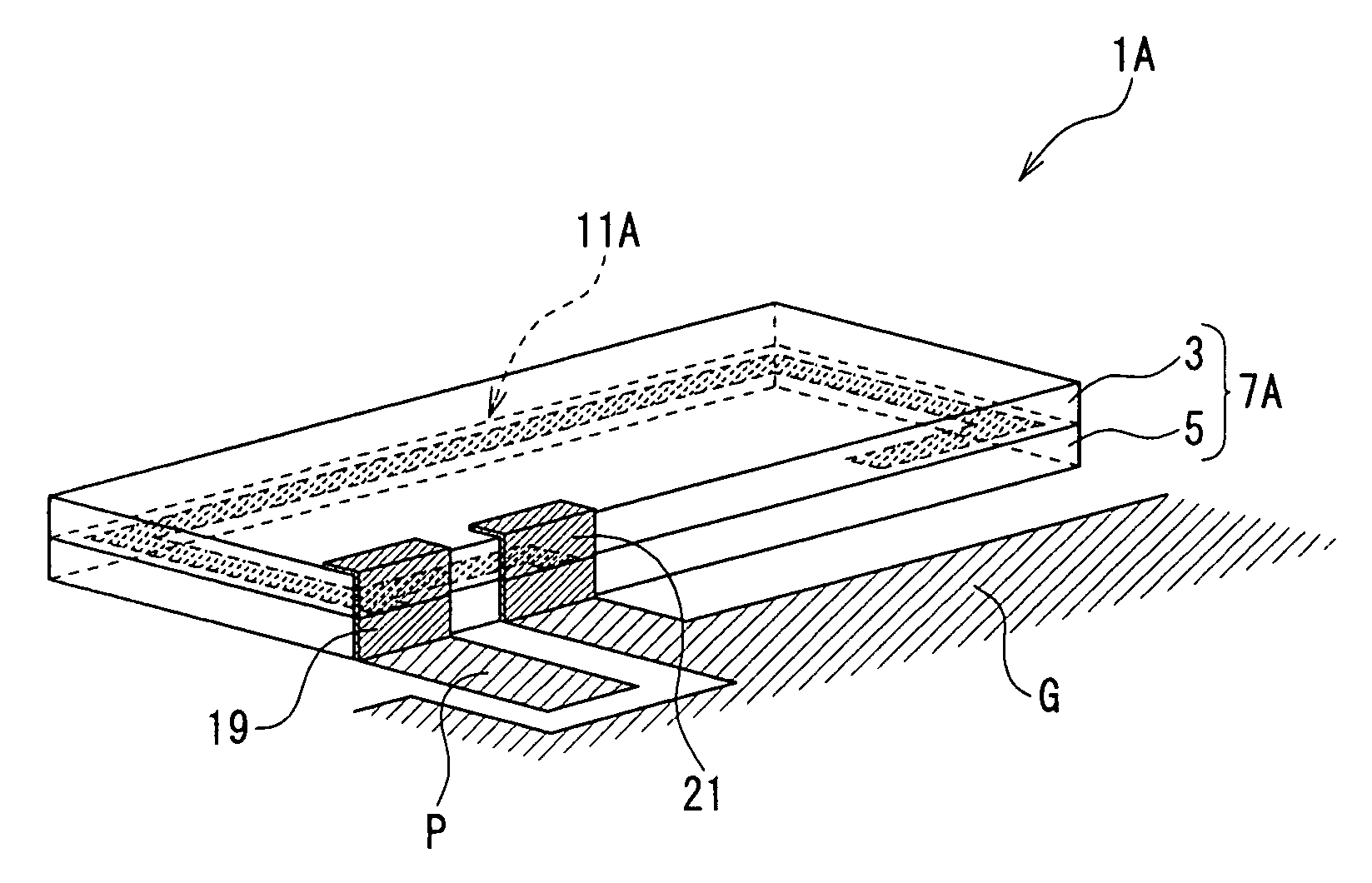
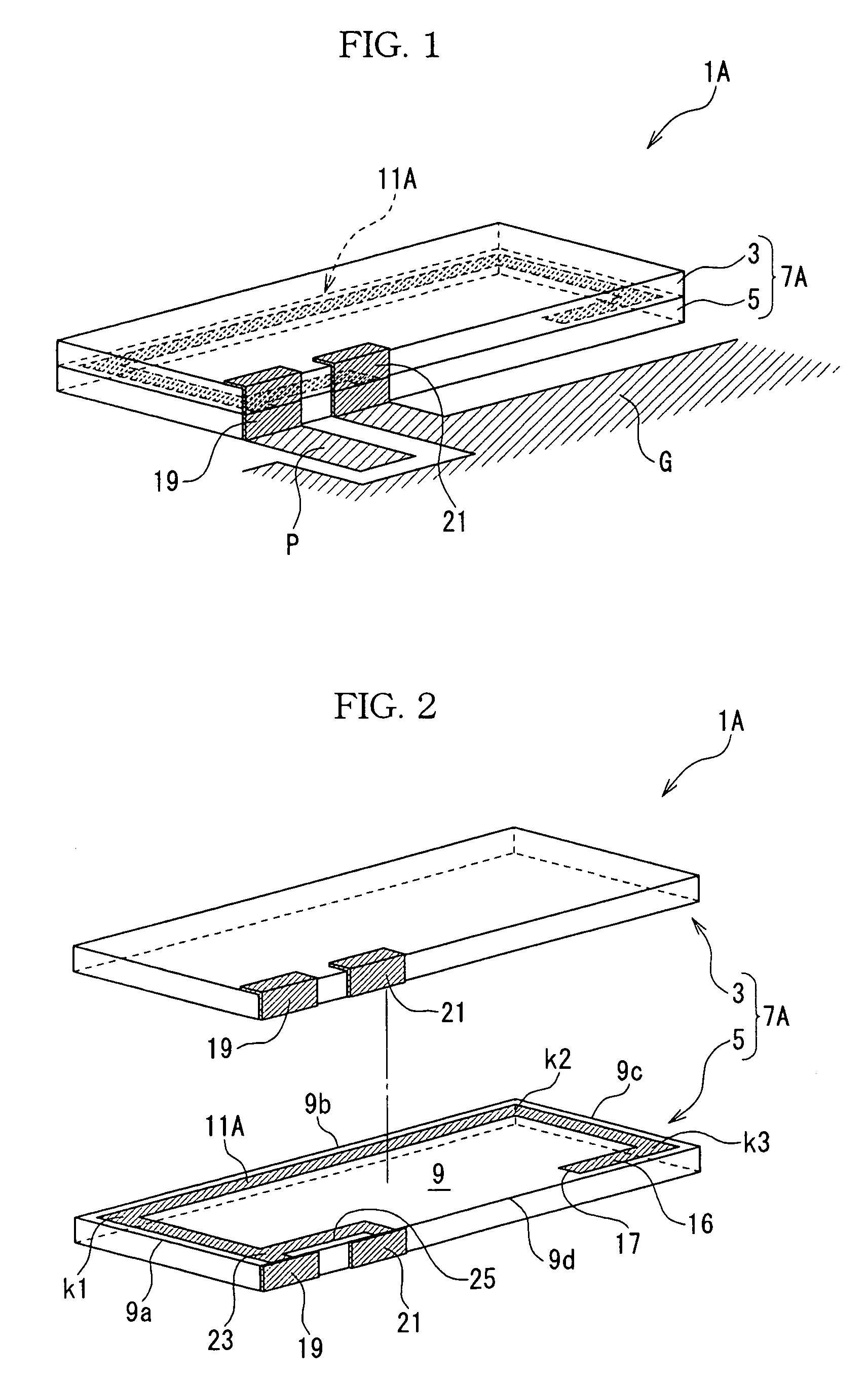
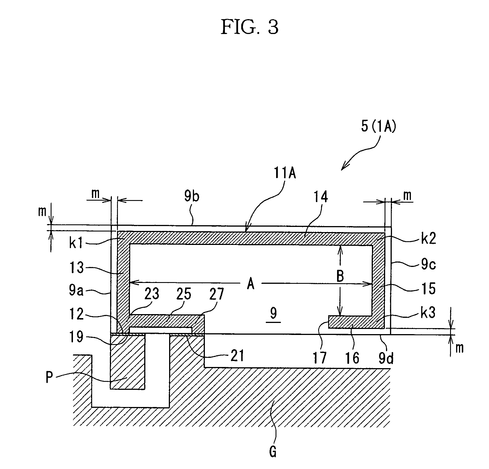
[0105]A dielectric antenna will be explained based on FIGS. 1 to 3. A dielectric antenna 1A has a dielectric base 7A formed by layering an upper substrate 3 and a lower substrate 5, which are insulating and composed of a dielectric ceramic material. The upper substrate 3 and the lower substrate 5 are formed in a rectangle (quadrangle) having the same size when observed in a plan view, so that the dielectric base 7A formed by layering the both becomes a rectangular parallelepiped shape. A front face of a top face (a face opposing the upper substrate 3) of the lower substrate 5 forms an antenna forming face 9 for forming an antenna. Since the lower substrate 5 is a rectangle, the antenna forming face 9 is also a rectangle (quadrangle). The reason of forming the dielectric base 7A by a multi-layered body is that an element and so on (described later) to be formed on the lower substrate 5 are preferred to be covered by the upper substrate 3 for protection. The dielectric base 7A is for...

second embodiment

[0119]The linear element 11E in the second embodiment is formed to have the length (¼ wave length) capable of resonating at the first frequency (first frequency band) as described above, and the linear sub-element 91E is formed to have the length capable of resonating at the second frequency (second frequency band) which is different from the first frequency. A relationship between the first frequency and the second frequency is determined according to an intended purpose of the dielectric antenna 1E. Specifically, as shown in FIG. 10a, when the resonance frequency F1 of the linear element 11E and the resonance frequency F2 of the linear sub-element 91E are set close to each other so as to obtain, for example, a band F at VSWR2 or lower, formation of the linear sub-element 91E can make the frequency band of the entire dielectric antenna 1E to be a wider band as compared to the case of not forming the linear sub-element 91E. Further, as shown in FIG. 10b, by moderately separating the...

fifth embodiment

[0168]A modification example of the fifth embodiment will be explained with reference to FIGS. 32 and 33. A dielectric antenna 1R according to this modification example is different from the dielectric antenna 1P shown in FIG. 29 in a connection form of elements. Here, the difference will be explained, and explanation of common points is omitted. Specifically, the dielectric antenna 1R has a dielectric base 7R formed by layering an upper substrate 3, a middle substrate 4, and a lower substrate 5, which are insulating and composed of a dielectric ceramic material. On a first antenna forming face 9 which the middle substrate 4 has, there is formed a first linear element 11R which is adjacent to (parallel to) peripheries, 9a, 9b, 9c, and 9d of the first antenna forming face 9. A reference numeral 25 shown in FIG. 32 denotes a linear conductor for matching impedance which is connected to the first linear element 11R.

[0169]On a second antenna forming face 10 which the lower substrate 5 h...


PUM


Abstract

On an antenna forming face (9) in a rectangular shape which a dielectric base (7A) has, a linear element (11A) is provided adjacently only peripheries (9a, 9b, 9c, and 9d) of the antenna forming face (9). From the linear element (11A), a linear conductor (25) for matching impedance branches. Since the linear element is adjacent to only the peripheries (9a, 9b, 9c, and 9d) of the antenna forming face (9), portions of the linear element (11A) do not become adjacent to each other. Accordingly, mutual interference which easily occurs when the portions of the linear element (11A) are adjacent to each other does not occur, so that decrease of radiation efficiency of the dielectric antenna (1A) and hindrance to widening a band thereof can be eliminated as much as possible.

Description

TECHNICAL FIELD[0001]This application is a 371 of PCT / JP03 / 08516 filed on Jul. 4, 2003.[0002]The present invention relates to a dielectric antenna, which is included in a mobile communication device represented by cellular phones, portable radio communication devices and the like, an antenna mounting substrate, and a mobile communication device including them.BACKGROUND ART[0003]In accordance with the popularization of mobile communication devices in recent years, miniaturization and weight reduction of them are desired for making them convenient for carrying or moving. Among electronic parts included in such a mobile communication device, miniaturization of semiconductor integrated circuit or the like is in rapid progress.[0004]However, miniaturization of antenna is not being advanced, which hinders the miniaturization and weight reduction of mobile communication devices. Japanese Patent Laid-open No. 2000-196339 discloses an element formed in a spiral or a meander shape for miniat...

Claims


Application Information

Patent Timeline
IPC IPC(8): H01Q1/38H01Q1/24H01Q1/40H01Q5/00H01Q5/371H01Q5/378H01Q9/04H01Q9/42
CPCH01Q1/243H01Q1/38H01Q1/40H01Q5/378H01Q9/0485H01Q9/42H01Q5/371H01Q9/0421
Inventor OKADO, HIRONORI
Owner TAIYO YUDEN KK
Why Eureka
Try Eureka