Head tracker system

Inactive Publication Date: 2006-05-16
BAE SYSTEMS PLC
View PDF20 Cites 53 Cited by
  • Summary
  • Abstract
  • Description
  • Claims
  • Application Information

AI Technical Summary

Benefits of technology

[0022]In accordance with a particularly preferred embodiment for use in an aircraft, said environment comprises at least a part of the cockpit such as the instrumentation. To further assist in the optical correlation process and to provi

Problems solved by technology

For example, early tracking systems used mechanical linkages between the helmet and the vehicle and, whilst such systems were relatively accurate, they were cumbersome, restricted the user's movement and posed particular problems during ejection from an aircraft.
For example, although inertial systems based on gyroscopes have a very fast dynamic response, the accuracy of these systems is limited by drift over extended periods of operation.
Tracker systems which are based on magnetic

Method used


Image

  • Head tracker system
  • Head tracker system
  • Head tracker system

Examples


Embodiment Construction

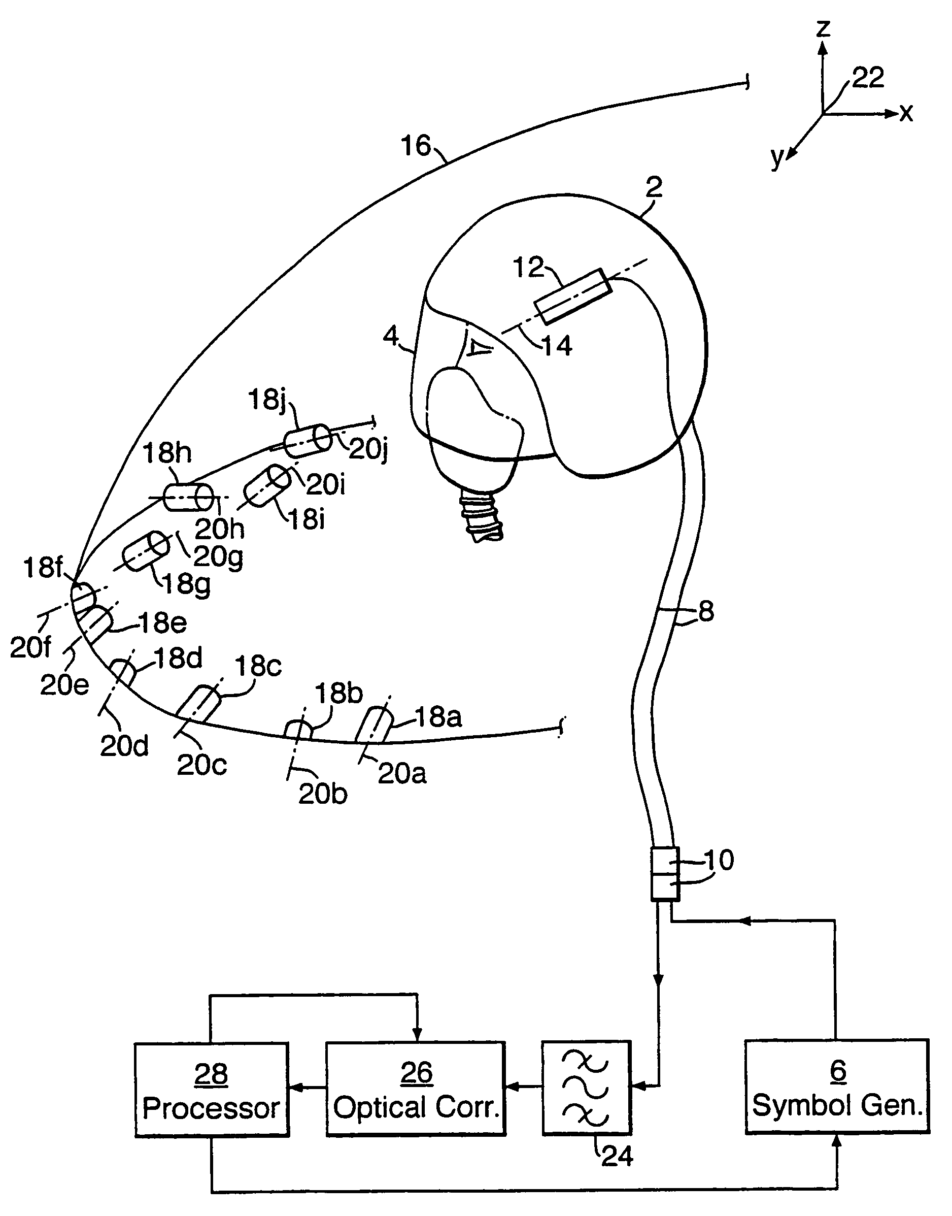
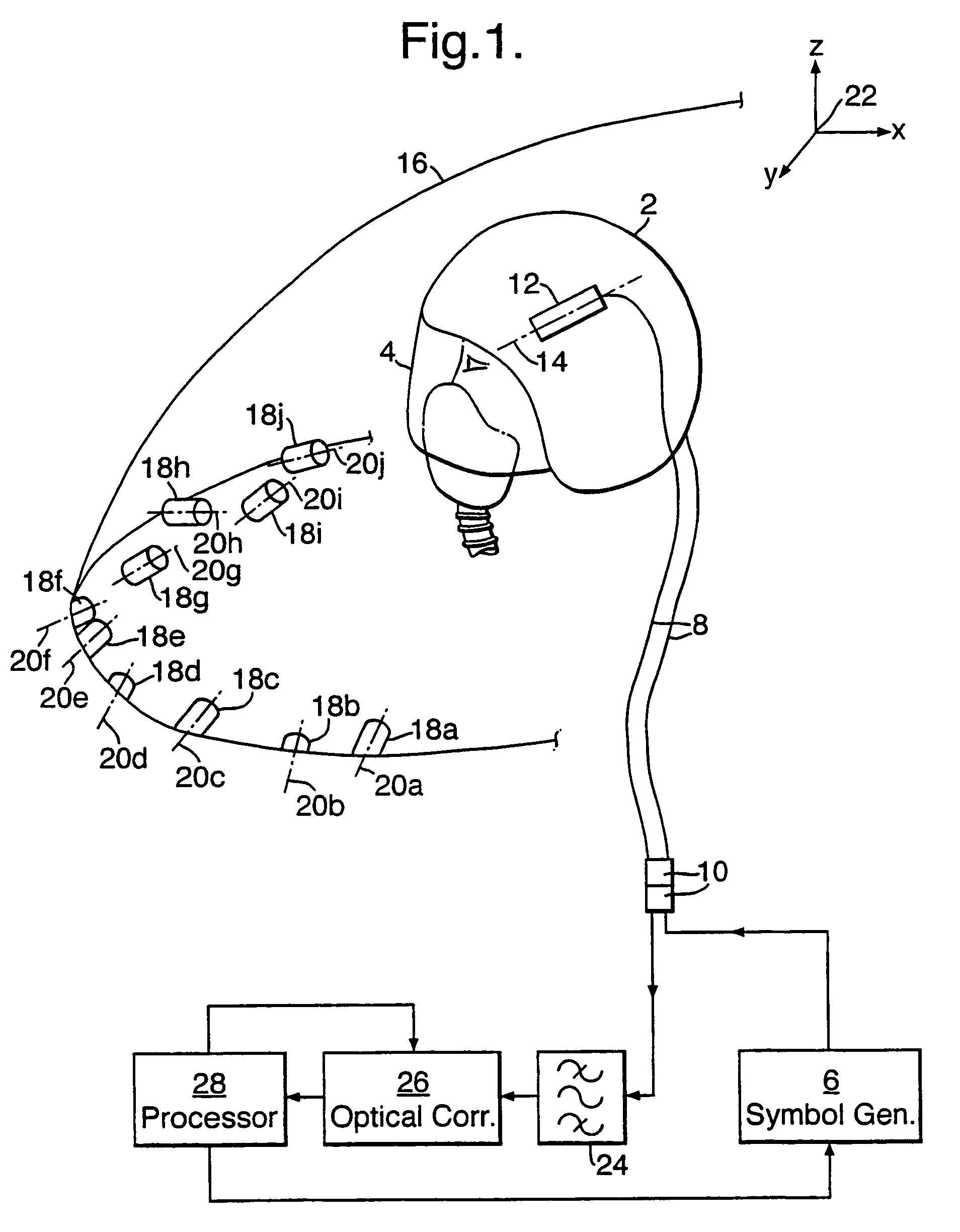
[0026]Referring to FIG. 1 there is shown a head tracker system for use in a fixed wing aircraft which comprises a helmet 2 which constitutes a head mounting for attachment to a pilot's head. In a known manner the helmet 2 is provided with a visor 4 and internally the helmet is provided with a helmet mounted display (HMD) device (not shown) which is arranged to project a display onto a partially reflective inner surface of the visor 4 so that the display is superimposed upon at least a part of the view seen by the pilot through the visor 4. In an alternative arrangement the HMD device can project a display onto discrete eye pieces which are located within the line of sight of the pilot. As is known the symbology displayed on the HMD generated by a symbol generator 6 which is located within the aircraft. The symbology is appropriately referenced in dependence on the user's head orientation which is determined by a processor 28 which is described below. The signals used to drive the HM...


PUM


Abstract

A head tracker system for determining a user's head orientation relative to a datum (22) comprises: a head mounting (2) for attachment to the user's head; an optical sensor (12) which in use is located in fixed relation with a known fixed point relative to the head mounting (2) and a plurality of distinguishable markings (18a–18j) each of which when in use is located in fixed relation with a respective known point which is fixed relative to the datum (22). The head tracker further comprises an optical correlator (26) for optically correlating the optical image from the optical sensor (12) with an optical image representative of at least one of said markings (18a–18j); and means (28) for determining the orientation of the head mounting using the output from the optical correlator when it detects that there is correlation between the images.

Description

[0001]This application is the U.S. national phase of international application PCT / GB00 / 00729, filed in English on 1 Mar. 2000, which designated the U.S. PCT / GB00 / 00729 claims priority to GB Application No. 9904669.0 filed 1 Mar. 1999 and GB Application No. 9917582.0 filed 28 Jul. 1999. The entire contents of these applications are incorporated herein by reference.BACKGROUND OF THE INVENTION[0002]1. Field of the Invention[0003]This invention relates to a head tracker system and more especially, although not exclusively, to a head tracker system for use in an aircraft in which the pilot is provided with a helmet-mounted display.[0004]2. Discussion of Prior Art[0005]Head tracker systems are well known and operate to determine a user's head orientation and position relative to a fixed datum. Originally these systems were developed for use in military aviation but have recently found applications in virtual reality systems.[0006]Since the earliest days of military aviation, pilots have ...

Claims


Application Information

Patent Timeline
IPC IPC(8): G09G5/00G01S5/16G02B27/00G02B27/01G06F3/00G06F3/01G09B9/30
CPCG01S5/163G02B27/0093G09B9/307G02B27/0172G06F3/012G02B27/017
Inventor BARTLETT, CHRISTOPHER T
Owner BAE SYSTEMS PLC
Why Eureka
Try Eureka