In-plane field type liquid crystal display device comprising liquid crystal molecules with more than two kinds of reorientation directions

a liquid crystal display device and in-plane field technology, applied in non-linear optics, instruments, optics, etc., can solve the problems of narrow isochromaticity range, inability to achieve the same viewing angle characteristics as self-, and achieve the effect of greatly reducing the dependence of viewing angle on color tone chang

Inactive Publication Date: 2006-05-16
PANASONIC LIQUID CRYSTAL DISPLAY CO LTD +1
View PDF17 Cites 17 Cited by
  • Summary
  • Abstract
  • Description
  • Claims
  • Application Information

AI Technical Summary

Benefits of technology

[0015]That is, when liquid crystal molecules are twisted by rotation and viewing angle is tilted to the major-axis direction of the molecules, the birefringence anisotropy of the liquid crystal molecules more easily changes compared with the case of tilting the viewing angle to other directions, so that gradation level is more easily inverted and color tone more easily changes in the major-axis direction than in other directions.
[0018]The present invention has been made to solve the above mentioned problems of the prior art and its object is to provide an art for realizing wide viewing angle characteristics equal to those of a CRT and improving the image quality for an active-matrix liquid crystal display device using the in-plane field type.
[0047]According to the above means, shifts of color tones are offset each other and the dependency of color-tone on a viewing angle can greatly be reduced because the initial orientation angle φ LC is made different for neighboring picture elements or in one picture element so as to form two or more kinds of reorientation directions.
[0053]Therefore, by rotating liquid crystal molecules in two directions for each picture element or in one picture element, and by creating two reorientation states where the major-axis directions of the two states are nearly perpendicular to each other in displaying a white image or a half-tone image, color tones of the two states are offset each other and the viewing angle dependency of color tone change can greatly be reduced.

Problems solved by technology

However, the active-matrix liquid crystal display device using the in-plane field type cited above has a problem that viewing angle characteristics equal to those of a self-light-emitting display device such as a cathode ray tube (CRT) cannot be achieved because a homogeneous color tone cannot be realized and the viewing angle range of isochromaticity narrows when tilting a viewing angle to a certain direction.

Method used


Image

  • In-plane field type liquid crystal display device comprising liquid crystal molecules with more than two kinds of reorientation directions
  • In-plane field type liquid crystal display device comprising liquid crystal molecules with more than two kinds of reorientation directions
  • In-plane field type liquid crystal display device comprising liquid crystal molecules with more than two kinds of reorientation directions

Examples


example 1

[0377]In the case of this embodiment, both angles of the bent portions of the pixel electrodes and counter electrodes are set to 170° as shown in FIG. 18.

[0378]The gap distance between a pixel electrode and a counter electrode is the same in all picture element and it is set to 30 μm.

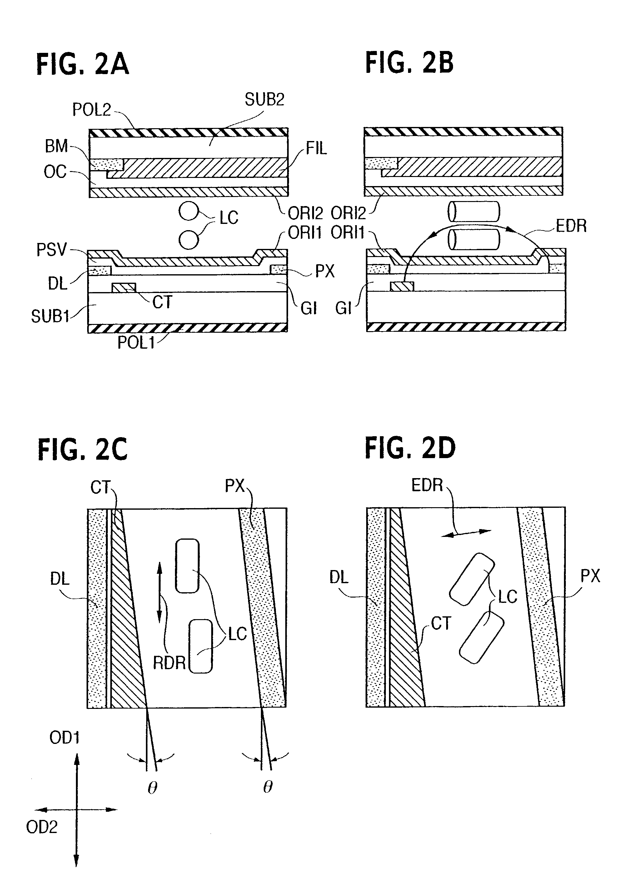
[0379]Rubbing directions on top and bottom orientation films sides are almost parallel each other and also vertical to scanning signal lines.

[0380]The polarized-light transmission axis of one polarizing plate is made almost parallel with the rubbing direction and that of the other polarizing plate is made perpendicular to the rubbing direction. Thereby, the normally black mode is obtained.

[0381]Viewing angle characteristics of the panel thus manufactured are evaluated within ±60° of φ by using an inspection apparatus (Model C5718 made by HAMAMATSU PHOTONICS Co., Ltd.).

[0382]By displaying images of eight gradations and measuring the viewing angle dependency of brightness at each gradation, no tone revers...

example 2

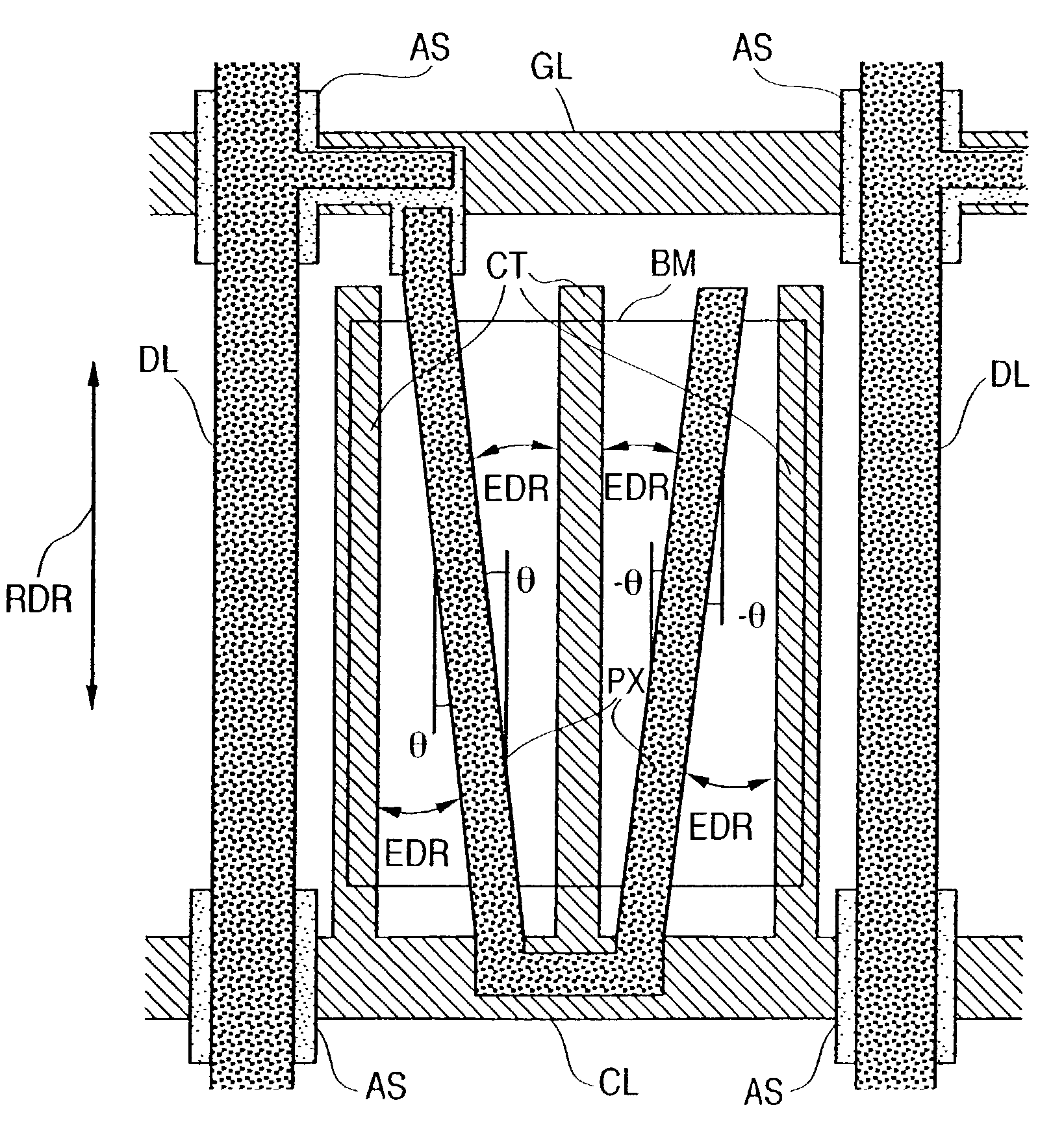
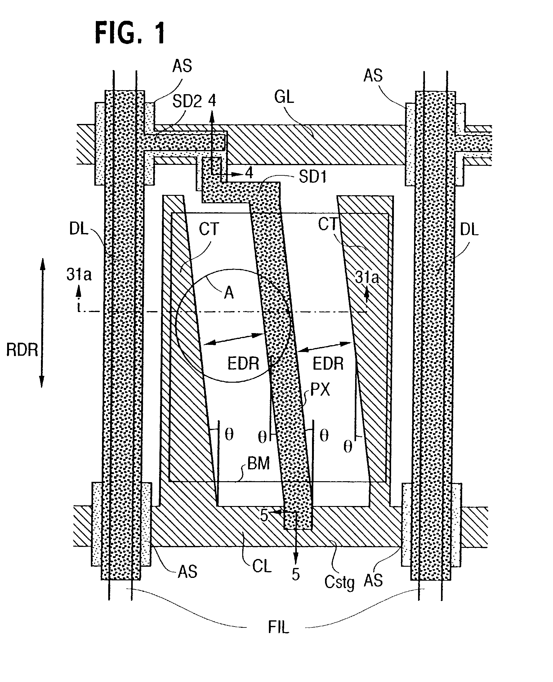
[0383]FIG. 19 is an illustration showing another example of this embodiment in the unit picture element.

[0384]The liquid crystal display device is manufactured similarly to example 1 except that shapes of two pixel electrode and three counter electrodes are changed as shown in FIG. 19 and the gap distance between pixel electrodes and counter electrodes is changed to 15 μm.

[0385]As the result of measuring viewing angle characteristics similarly to the ease of example 1, no tone reversal occurred at any angle within ±60° of φ.

example 3

[0386]The liquid crystal display device is manufactured similarly to example 2 except that angles of the bent portions of pixel electrodes and counter electrodes are changed to 178°.

[0387]As the result of measuring viewing angle characteristics similarly to the case of example 1, no tone reversal occurred at any angle within ±60 of φ.

[0388]As the result of measuring a voltage at which the transmittance is maximized and a voltage at which the transmittance is equal to 1% of the maximum transmittance, voltages of 2.5 V and 1.5 V are obtained respectively. The difference between—the voltages is 1.0 V, which is remarkably small.


PUM

PropertyMeasurementUnit
angleaaaaaaaaaa
angleaaaaaaaaaa
angleaaaaaaaaaa

Abstract

An active matrix liquid crystal display device having a pair of substrates, a liquid crystal layer, scanning lines and video signal lines provided in a matrix manner, at least one pixel electrode and at least one common electrode. The at least one pixel electrode is bent so as to be inclined in first and second directions which are symmetrical relative to the alignment direction of the liquid crystal. The first direction of the pixel electrode is at a plus predetermined angle relative to the alignment direction, while the second direction of the pixel electrode is at a minus predetermined angle relative to the alignment direction.

Description

CROSS REFERENCE TO RELATED APPLICATION[0001]This is a continuation of U.S. application Ser. No. 09 / 841,100, filed Apr. 25, 2001, now U.S. Pat. No. 6,545,658 which is a continuation U.S. application Ser. No. 08 / 722,849, filed Sep. 26, 1996, now U.S. Pat. No. 6,266,116, the subject matter of which is incorporated by reference herein.BACKGROUND OF THE INVENTION[0002](1) Field of the Invention[0003]The present invention relates to a liquid crystal display device and its manufacturing method, particularly to an art to be effectively applied to an in-plane field type active-matrix liquid crystal display device.[0004](2) Description of the Prior Art[0005]An active-matrix liquid crystal display device using an active element such as thin film transistor (TFT) has been widely spread as a display terminal of OA equipment because it is thin and lightweighted and has a high image quality equal to that of a cathode-ray tube.[0006]The display system of the active-matrix liquid crystal display dev...

Claims


Application Information

Patent Timeline
Patent Type & Authority Patents(United States)
IPC IPC(8): G02F1/1343G02F1/1333
CPCG02F1/134363G02F1/133707G02F1/133528G02F1/133753G02F1/1362G02F1/137
Inventor OHTA, MASUYUKIYANAGAWA, KAZUHIKOOGAWA, KAZUHIROASHIZAWA, KEIICHIROYANAI, MASAHIROKONISHI, NOBUTAKEKONDO, KATSUMIOHE, MASAHITOARATANI, SUKEKAZUKLAUSMANN, HAGEN
Owner PANASONIC LIQUID CRYSTAL DISPLAY CO LTD
Why Eureka
Try Eureka