Method and system for span optical power control

a technology of optical power control and span, applied in the field of balancing power, can solve problems such as dangerous overpowering and optical power control concep

Active Publication Date: 2006-05-16
ECE TELECOM LTD
View PDF10 Cites 16 Cited by
  • Summary
  • Abstract
  • Description
  • Claims
  • Application Information

AI Technical Summary

Benefits of technology

[0031]in case of a difference between the expected total input power and the real total input power at said particular OADM exceeds a predetermined value, controlling power of each of added channels of said OADM to follow said difference, thereby to equalize output power of all optical channels outgoing from said OADM.

Problems solved by technology

1. the principle of fixed output power (when the fixed output power is divided to a required number of the output channels—which leads to underpowering if the number of channels is max, and to a very dangerous overpowering where the number of output channels is low, say in a case of fiber cut before an OADM that adds few channels into an OFA.
2. the principle of fixed power dependent on the number of channels, wherein the amplifier output power is controlled with respect to the number of channels, so as to provide a fixed output power per channel. (for example, one channel—1 mW, 15 channels 15 mW, 40 or more channels—40 mW max). In the known technologies, the number of channels is usually stated (say, by an operator) from time to time.
3. the principle of fixed gain; according to that, the amplifier has a fixed gain so that each channel, whatever input power exists in it, is amplified with the same gain as other channels. To maintain the required output power, it is known to arrange a feedback loop measuring, the input and the output power and, based on the result, capable of regulating the output power of the amplifier. In the fixed gain scheme, in order to obtain equal and fixed output powers of the channels at the output of the amplifier, it is only possible to ensure that the input powers be equal and fixed. To maintain the condition, it is known to insert a VOA (Variable Optical Attenuator) into the input optic fiber, to adjust the input power of the optical channels which arrive to the amplifier.
The problem stems from the facts that a) no dynamic monitoring of the chain parameters has been proposed, and b) elements of the chain may be different and thus behave differently, but no common concept of optical power control has been proposed for such a chain.

Method used


Image

  • Method and system for span optical power control
  • Method and system for span optical power control
  • Method and system for span optical power control

Examples


Embodiment Construction

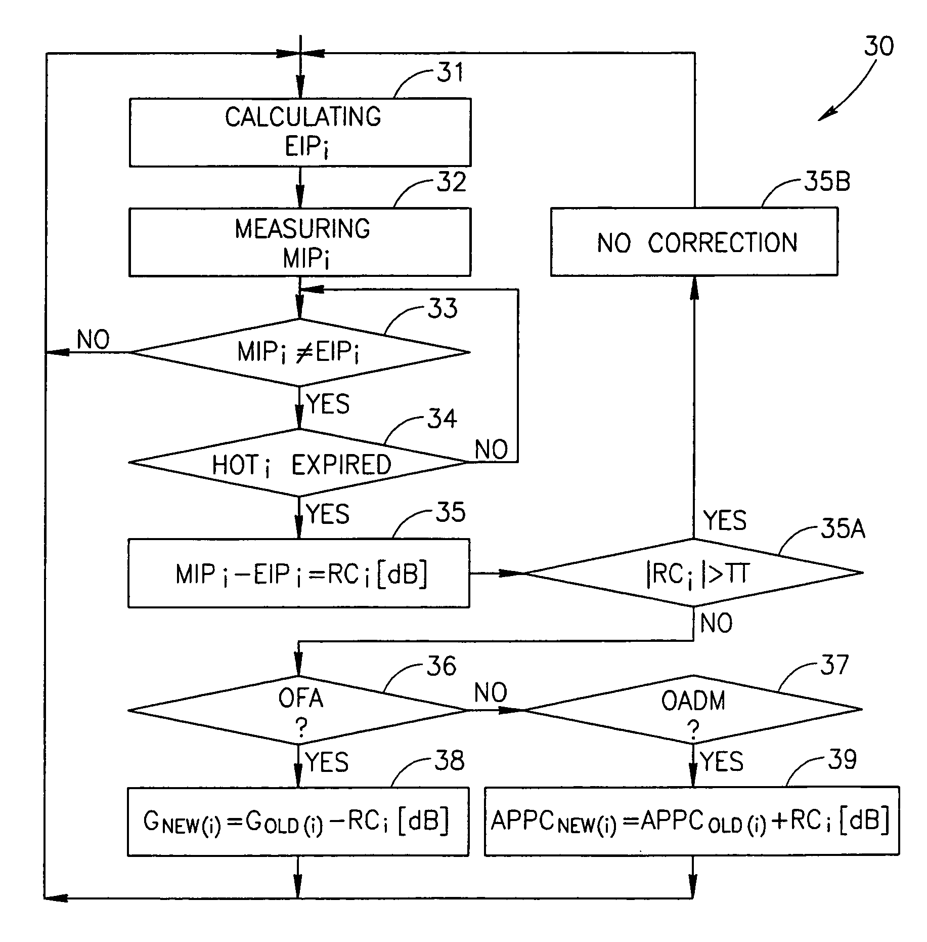
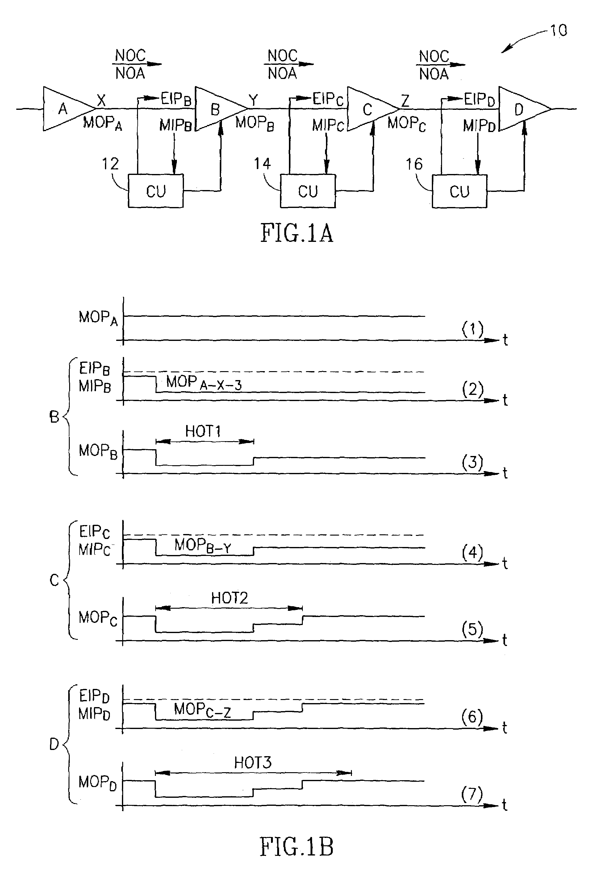
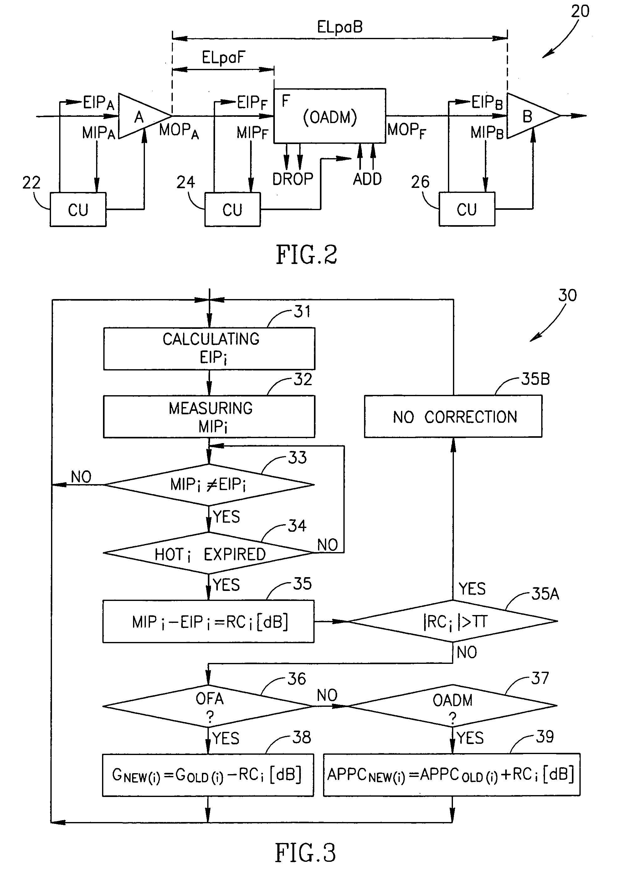
[0073]The method described in the present application starts from a preliminary step of designing (pre-configuring) an optical communication line, comprising optical amplifiers and OADMs, by stating gains of the optical amplifiers, span losses, stating initial values of NOC and NOA for any point in the line, and also an expected output power per channel for each optical amplifier OFA. This expected output power per channel is further maintained to be constant.

[0074]The line is preliminarily designed (configured) and calculated to ensure, at each point thereof, the balanced (i.e., constant or equalized) power per optical channel in each span of the line at normal (predictable) conditions of the line's operation. The normal or predictable conditions are characterized by the following groups of parameters:

[0075]a) configuration parameters which must not change during the routine operation (nominal gains of the amplifiers; noise figures introduced by the amplifiers; span losses i.e., va...


PUM


Abstract

There is proposed a method and a module for real time control of power per optical channel in a multi-channel optical communication line formed by a group of optical elements connected in a chain by fiber spans. The group of elements comprises one or more optical fiber amplifiers (OFA); each of the spans is characterized by its span loss, while each of the OFA is characterized by its gain and its designed output power per channel. The method comprises steps of calculating an expected total input power value (EIP) for a particular optical amplifier (OFA) in the line, measuring a real total input power (MIP) at the particular optical amplifier, and comparing the values. If a difference between the EIP and the MIP at the OFA exceeds a predetermined value, the method (and the module) ensures adjusting the gain of the OFA to maintain its output power per channel constant.

Description

FIELD OF THE INVENTION[0001]The present invention relates to a technique of balancing power provided at the output of a network element handling multiple optical channels and being part of a chain of network elements in a telecommunication line.BACKGROUND OF THE INVENTION[0002]Those skilled in the art are familiar with a problem that, in a point-to-point optical communication line (which comprises a number of network elements, such as optical fiber amplifiers OFA connected in series, and possibly, one or more optical add-drop multiplexers OADMs), one should pay attention to power equalization between multiple optical channels outputted by one network element to be sent to another one.[0003]The amplifiers may work according to one of the following principles:[0004]1. the principle of fixed output power (when the fixed output power is divided to a required number of the output channels—which leads to underpowering if the number of channels is max, and to a very dangerous overpowering ...

Claims


Application Information

Patent Timeline
Patent Type & Authority Patents(United States)
IPC IPC(8): H04B10/12H04B10/293H04J14/02
CPCH04B10/2931H04J14/0221H04J14/0206H04J14/0201
Inventor HALEVI, ILANSIVAN, TSVITUBY, MORDECHAYHARRIS, DAVID
Owner ECE TELECOM LTD
Why Eureka
Try Eureka