Optical waveguide, holographic medium, holographic storage and retrieval method and system

a technology of optical waveguides and holographic storage, applied in the field of optical waveguides, holographic mediums, holographic storage and retrieval methods and systems, can solve the problems of insufficient storage of data in the storage layer, inability to perform holographic storage and retrieval operations under preferable conditions, and large and expensive mechanisms, etc., to achieve convenient and highly accurate control of incident angles

Inactive Publication Date: 2006-05-16
NIPPON TELEGRAPH & TELEPHONE CORP
View PDF27 Cites 18 Cited by
  • Summary
  • Abstract
  • Description
  • Claims
  • Application Information

AI Technical Summary

Benefits of technology

[0031]In consideration of the above circumstances, an object of the present invention is to provide a holographic storage and retrieval method and system for easily and highly-accurately controlling the incident angle of a reference beam, where the reference beam is input from the outside of a holographic medium in both the storage and retrieval processes which employ multiple angles.

Problems solved by technology

Therefore, a large and expensive mechanism is necessary.
However, in the media shown in FIGS. 74 and 76, the above-explained evanescent light generally has a low light intensity; thus, data may not be sufficiently stored in the storage layer.
As a result, the holographic storage and retrieval operation cannot be performed under preferable conditions.
Therefore, the intensity of the reference beam (i.e., the evanescent light) attenuates while the input beam proceeds from the input face, thereby producing insufficient data storage in the storage layer 4.
Additionally, in the medium shown in FIG. 76, the storage layer 4 should be provided for each core layer 1; thus, the entire structure and manufacturing processes are complicated, thereby increasing the manufacturing cost.
In addition, the medium shown in FIG. 77 is a retrieval-only medium; thus, additional data storage or revision of stored data is impossible.
However, in the conventional optical waveguide, a light beam in free space, that is, the diffracted beam 105 diffracted by the diffraction grating layer 102 has a light intensity profile which is not uniform through the layer; thus, it is difficult to handle this kind of optical waveguide as an optical component.

Method used


Image

  • Optical waveguide, holographic medium, holographic storage and retrieval method and system
  • Optical waveguide, holographic medium, holographic storage and retrieval method and system
  • Optical waveguide, holographic medium, holographic storage and retrieval method and system

Examples


tenth embodiment

[0384]FIG. 21 is a diagram showing the structure of a holographic storage and retrieval system as the tenth embodiment of the present invention. In each embodiment explained below, the holographic storage and retrieval system may be divided into a storage system having a storage function and a retrieval system having a retrieval function.

[0385]The holographic storage and retrieval system comprises a light source 50, two beam splitters 511 and 512, a spatial optical modulator 52, a photodetector 53, two imaging devices 541 and 542, three reflectors 551, 552, and 553, a condenser 56, three polarization controllers 571, 572, and 573, three beam shutters 621, 622, and 623, and two spatial optical selectors 631 and 632.

[0386]The light source 50 is typically a light source for emitting a light beam such as laser.

[0387]Each of the beam splitters 511 and 512 includes a half mirror, any kind of beam splitter, or the like and is provided for splitting a beam into two beams.

[0388]The spatial o...

eleventh embodiment

[0422]FIG. 24 is a diagram for explaining the incident angle control method as the eleventh embodiment of the present invention.

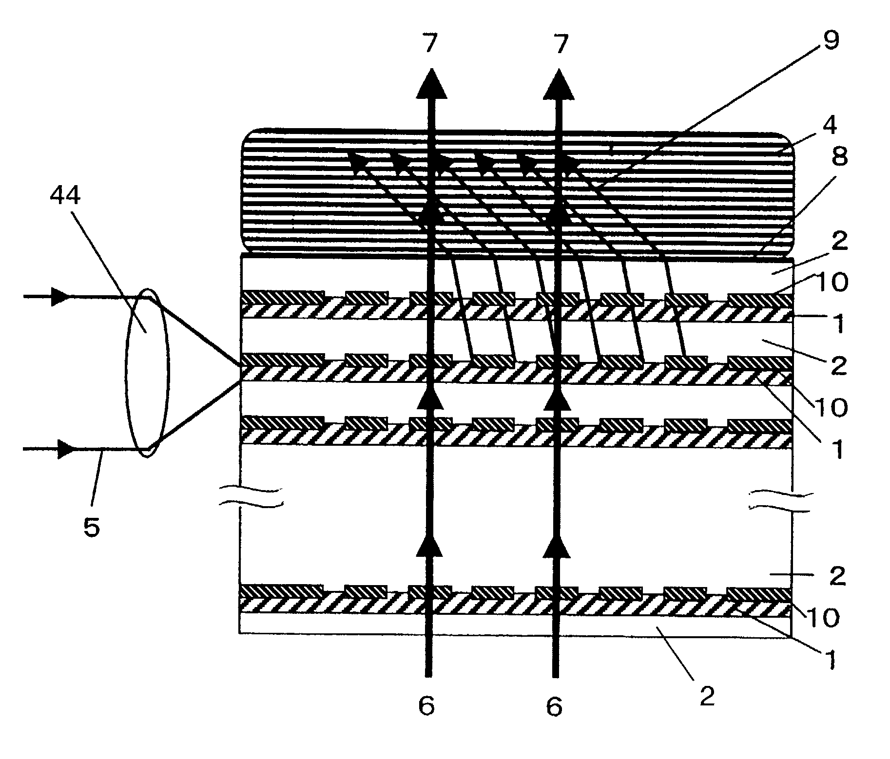
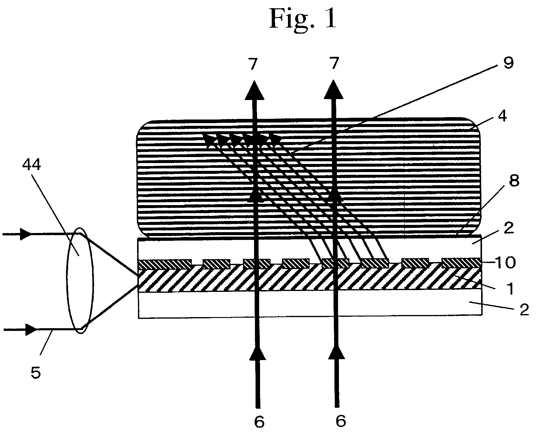
[0423]In FIG. 24, the diffraction grating layer 3 is designed so that a reference beam 5 incident at the above-explained angle θ0 is diffracted and emitted at a specific angle, and each value of angle θ0 is assigned to each of the diffraction grating layers 3, 3, . . . 3 in a one-to-one corresponding relationship.

[0424]That is, when the reference beam 5 is incident at any angle θ0, the reference beam 5 is coupled with any one of the diffraction grating layers 3, 3, . . . 3 which corresponds to this angle θ0 and is transmitted as a transmitted beam 500 through the core layer 1 for which said one of the diffraction grating layers is provided. Therefore, the transmitted beam 500 is output as an emitted beam 110 only from an end face of this core layer 1.

[0425]Either or both of the reference beam 5 and the optical waveguide 123 (see FIG. 24) may be shifted and / ...

twelfth embodiment

[0459]FIG. 30 is a diagram for explaining an incident angle control method as the twelfth embodiment of the present invention.

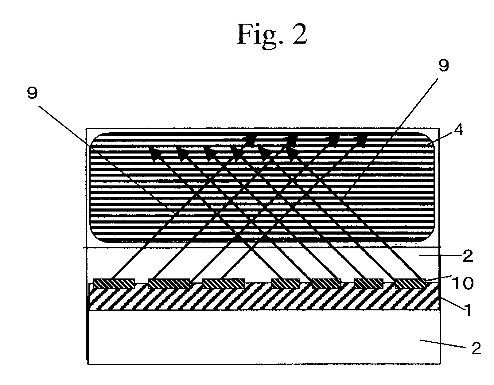
[0460]In FIG. 30, each diffraction grating layer 3 is designed to have a one-to-one corresponding relationship with each incident angle θ0. That is, when a reference beam 51 is input from an end face of a diffraction grating layer 3 which corresponds to a target incident angle θ0, a diffracted beam 9 is incident on the storage layer 4 at this incident angle θ0.

[0461]If the incident angle of a reference beam 5, which is incident from the lower side, coincides with the above incident angle θ0, the reference beam 5 and the diffracted beam 9 are parallel to each other. Therefore, one or both of the reference beam 5 and the optical waveguide 123 are shifted and / or rotated so as to make the reference beam 5 parallel to the diffracted beam 9 which corresponds to the target incident angle θ0, thereby controlling the incident angle of the reference beam 5 so as to mat...


PUM

PropertyMeasurementUnit
angleaaaaaaaaaa
refractive indexaaaaaaaaaa
index of refractionaaaaaaaaaa

Abstract

A holographic medium is formed of an optical waveguide including at least one core layer positioned between at least one portion of a material having a lower refractive index, a diffraction grating layer formed at a boundary between the core layer and the material of lower refractive index or in the core layer, and a storage layer outside the optical waveguide. Upon storing information in the storage layer a reference beam and an object are input into the optical waveguide and in retrieving stored information the reference beam is emitted to an end face of the core layer and transmitted through the core layer to be transformed into a diffracted beam in a diffraction grating layer that is emitted outside the core layer and transmitted through the storage layer, where the object beam is retrieved as a retrieved beam.

Description

BACKGROUND OF THE INVENTION[0001]1. Field of the Invention[0002]The present invention relates to an optical waveguide, a holographic medium using an optical waveguide, a method and system for controlling the angle of an incident beam onto such an optical device, and a holographic storage and retrieval method and system.[0003]2. Description of the Related Art[0004]Recently, holographic storage has become a focus of attention because of its capability of providing multiple data storage in a single medium, which produces high-density storage.[0005]A known concrete example of holographic multiple data storage methods is a so-called volume holographic method using multiple angles (refer to J. F. Heanue et al., “Volume Holographic Storage and Retrieval of Digital Data”, Science, vol. 265, pp. 749–752, 1994).[0006]FIG. 73 shows an example of a conventional volume holographic storage and retrieval method. In the figure, reference numeral 400 indicates a holographic medium made of an optical...

Claims


Application Information

Patent Timeline
Patent Type & Authority Patents(United States)
IPC IPC(8): G02B6/10G02B6/12G03H1/26G11B7/0065
CPCG03H1/0402G11B7/0065G03H1/26G02B2006/12107G03H1/0408G03H1/265G03H2001/0264G03H2222/47
Inventor YOSHIKAWA, HIROSHIANDOH, YASUKOITOH, KEIICHIROSENDA, MASAKATSUKUROKAWA, YOSHIAKITANABE, TAKAYA
Owner NIPPON TELEGRAPH & TELEPHONE CORP
Why Eureka
Try Eureka