Dual/triple redundant computer system

a computer system and triple redundant technology, applied in the field of computer systems, can solve the problems of safe or dangerous, human beings' safety, safe failure, etc., and achieve the effect of less expansive and sacrifice of system reliability

Inactive Publication Date: 2006-05-16
SUPERCON
View PDF12 Cites 58 Cited by
  • Summary
  • Abstract
  • Description
  • Claims
  • Application Information

AI Technical Summary

Benefits of technology

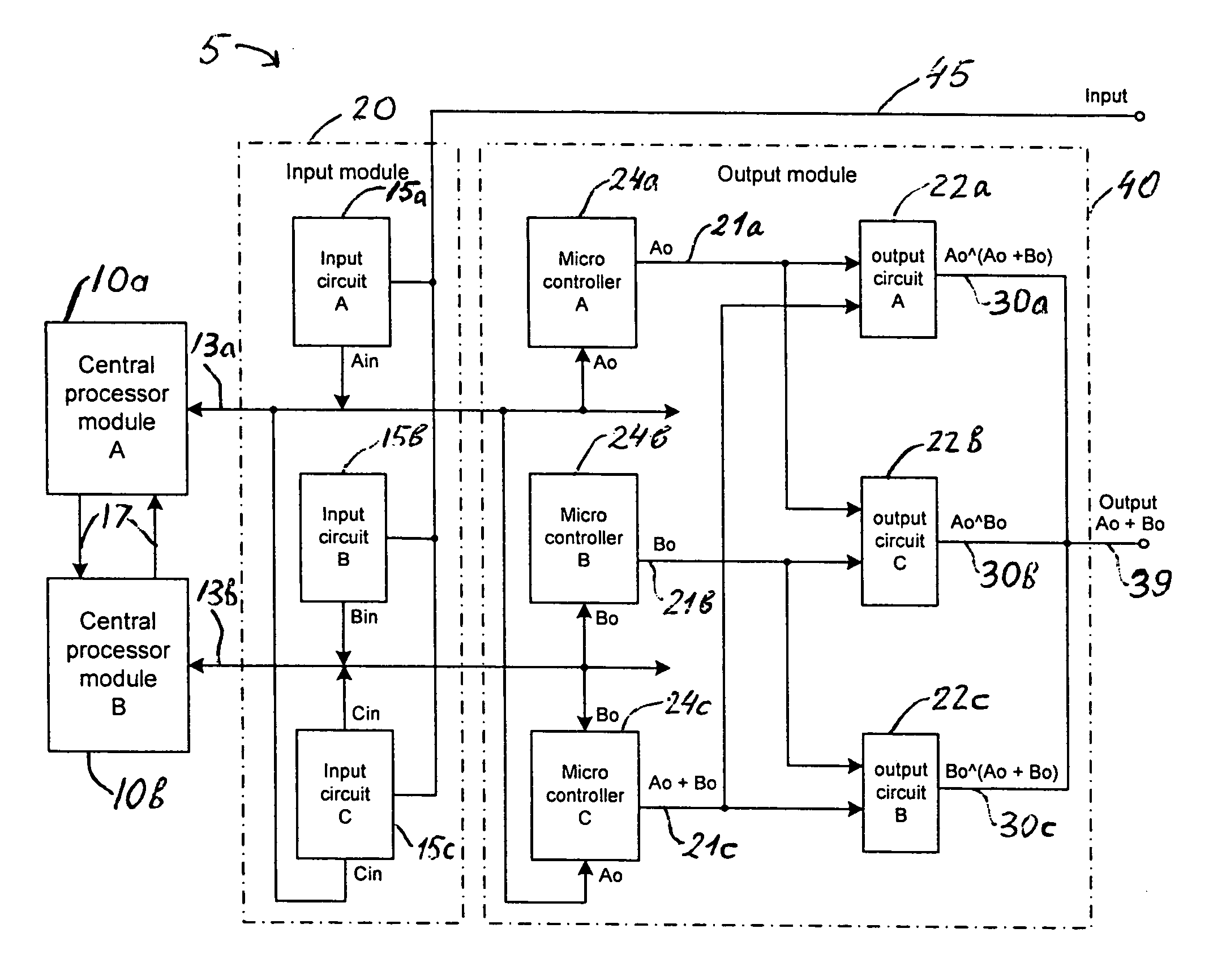
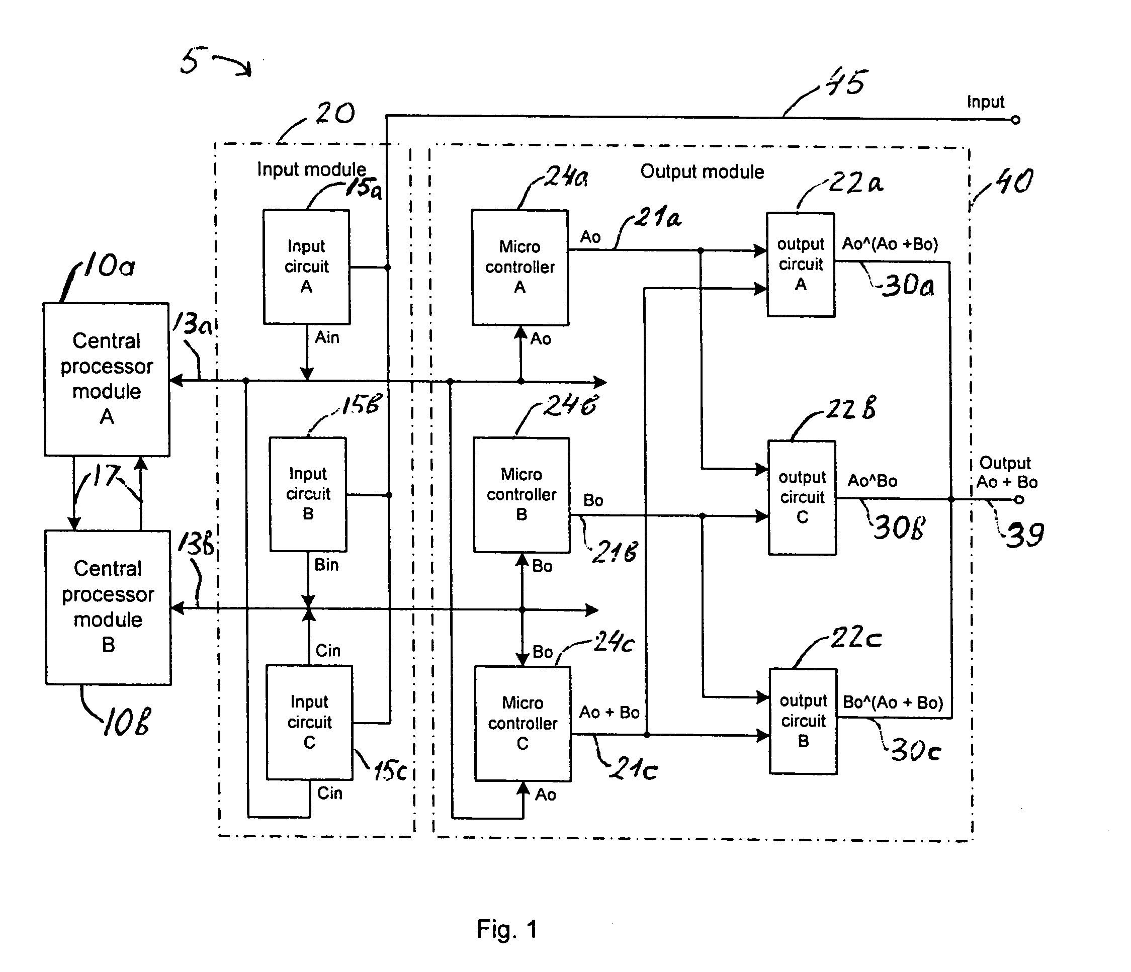
[0018]An object of the present invention, therefore, is an improved Dual/Triple Redundant Computer System that combines triple redundant I/O modules with dual redundant c

Problems solved by technology

Computer systems devoted to industrial safe and critical control applications must have extremely high degrees of safety and reliability since faults in computer systems can cause vast economic loses and endanger human beings.
A system failure that occurs as a result of a system component fault can be either safe or dangerous.
A safe failure occurs when a system has failed into a safe state, or in other words, where the system does not disrupt the operation of other systems or compromises the safety of personnel associated with the system.
The safe failure occurs, for example, when an emergency shutdown system (ESD) fails in such a way that it causes a shutdown not associated with the controlled process.
A dangerous failure is a failure that prevents the system from responding to hazardous situations, allowing hazards to develop.
For instance, a dangerous failure occurs when the ESD cannot perform a required shutdown.
In many cases, however, two concurrent faults lead to a system failure.
The primary difficulty with the TMR system is the voter.
In the event that two switches in series concurrently fail remaining in ON condition permanently, a dangerous failure occurs since the system becomes unable to make a shutdown if it is required.
In both of these scenarios the TMR system becomes inoperative as a result of two concurrent faults occurring.
The TMR system also may fail when two legs in the output module concurrently fails.
As well as the TMR, the 2oo

Method used


Image

  • Dual/triple redundant computer system
  • Dual/triple redundant computer system
  • Dual/triple redundant computer system

Examples


second embodiment

3. the System

[0096]The system 5 alternate embodiment (FIG. 3) comprises an input module 20a, an output module 40a, a first and a second central processor module 50a, 50b. The central processor modules 50 operate in parallel. The alternate embodiment also includes an input / output processor (IOP) 52. The central processor modules (CPM) 50a, 50b communicate each to other and to the IOP 52 over three communication links 17a, 17b, and 17c. The first and the second central processor module 50a and 50b also communicate with input module 20a and output module 40a via I / O buses 13a and 13b respectively. The IOP 52 communicates with input module 20a and output module 40a via I / O bus 13c.

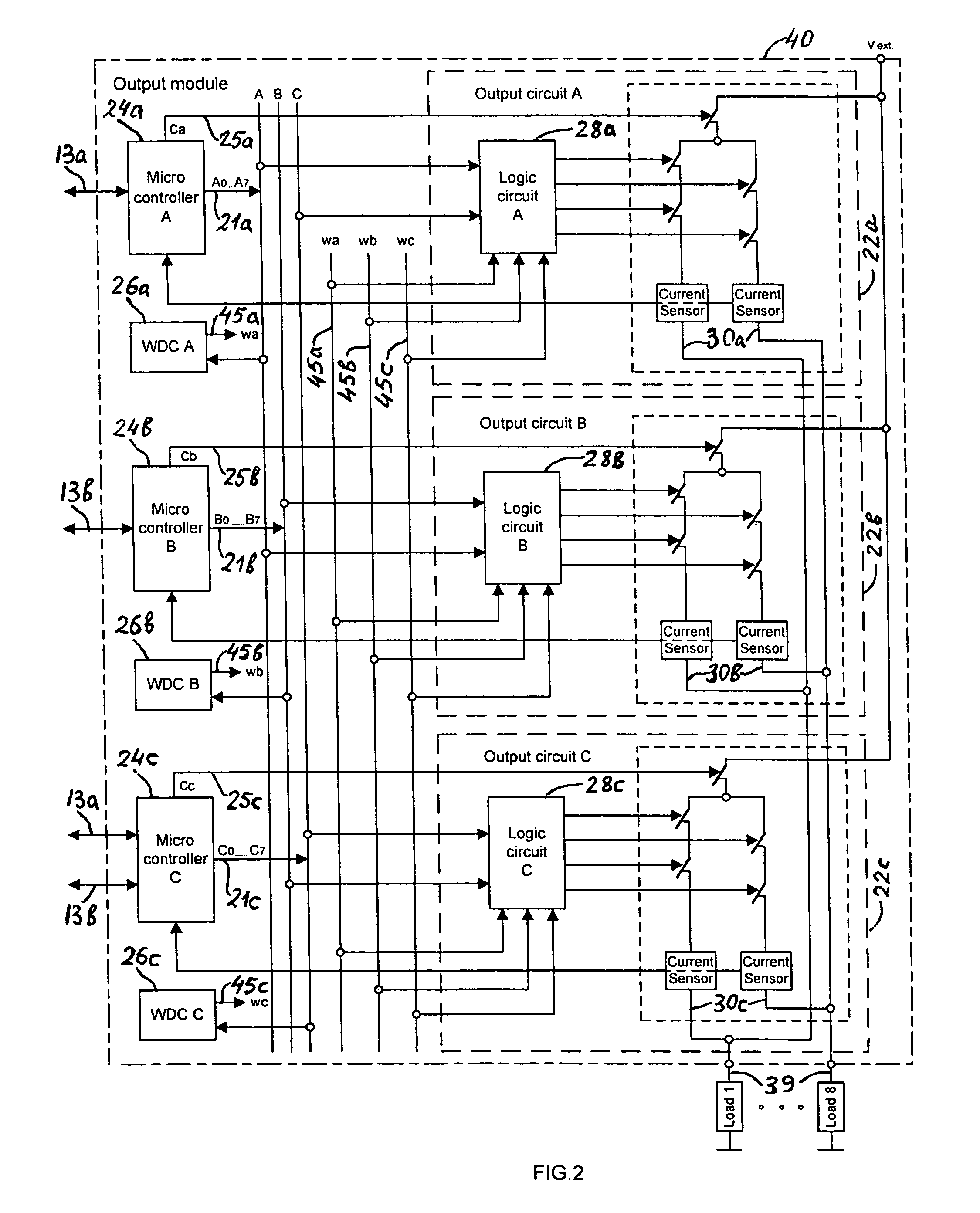
[0097]Referring to FIGS. 2 and 3, input modules 20 and 20a in the first and the second system embodiment are similar. A single difference between them is the input circuit 15c in the input module 20 is connected to both first and second CPM 10a, 10b, while the input module 20a is only connected to the IOP 52....

third alternate embodiment

4. The Third Alternate Embodiment

[0111]The third embodiment of the system 5 (FIG. 4a) comprises a first central processor module 60a, a second central processor module 60b and an input / output (I / O) subsystem 7. The I / O subsystem 7 can be located on a remote chassis and it is composed of an input module 20a and an output module 40a. The I / O subsystem 7 also includes communication links 17 and includes a first, a second and a third input / output processor (IOP) 29a, 29b, 29c. Each IOP 29 communicates with input module 20a and output module 40a over the associated I / O buses 13. The system 5 may be composed of a plurality of I / O subsystems 7, each of which, in turn, may consist of a plurality of input modules 20a and output modules 40a. The CPM 60a and the CPM 60b respectively communicate with each I / O subsystem 7 over I / O networks 9a and 9b.

[0112]Referring to FIGS. 2 and 4a, the first and the third embodiments employ the same configuration of input modules 20a and the same configuratio...

fourth alternate embodiment

5. The Fourth Alternate Embodiment

[0143]FIG. 5a depicts the fourth embodiment of the system 5. Referring to FIGS. 4a and 5a the third and the fourth embodiments employ the same I / O subsystem 7 that includes a plurality of I / O modules 20a, 40a and a first, a second, and a third input / output processors (IOP) 29a, 29b, 29c. The considered embodiment, however, differs with the third embodiment in that it operates in hot standby mode in regard to central processor modules 70 and it has an additional fault detector circuit (FDC) 90 for each central processor module 70. The FDC 90a and the FDC 90b communicate with its respective CPM 70 over associated communication links 51 and they communicate with each to other over communication links 55. Each FDC 90 includes an internal timer for monitoring operation of the neighboring FDC 90. This will become clear as the description proceeds.

[0144]In accordance with the well-known hot standby technique, one of the CPM 70 is on-line acting as a primar...


PUM


Abstract

A dual/triple redundant computer system having in one of the preferred embodiments triple redundant I/O modules and dual redundant central processor modules (CPM) that operate in parallel executing the same application program. Each input module includes three input circuits operating in parallel. The first CPM receives input data from first and third input circuits and transmits input data of the first input circuit to the second CPM. The second CPM receives input data from second and third input circuits and transmits input data of the second input circuit to the first CPM. Each CPM then performs a two-out-of-two vote among input data produced by first, second, and third input circuits and utilizes an outvoted data as input to the application program to provide output data by execution of the application program.
Each output module includes three microcontrollers operating in parallel. First and second microcontroller receives output data respectively from first and second CPM, while a third microcontroller receives at the same time output data from both first and second CPM. First microcontroller transmits output data to a first and a second output circuit. Second microcontroller transmits output data to second and third output circuit. The third microcontroller performs a selected logic operation among output data produced by first and second CPM and then transmits a result of this operation to third and first output circuits. Each output circuit generates a logical product of output data received from two associated microcontrollers. Outputs of first, second, and third output circuit are connected to each other for providing a two-out-of-three voting among output data produced by first, second, and third microcontroller, and for allowing the system to generate a system output as a result of a two-out-of-two voting of output data generated by first and second central processor modules.

Description

TECHNICAL FIELD[0001]The present invention relates generally to computer systems devoted to safety-critical and critical-control applications. More particularly, the present invention relates to multiple redundant systems that combine dual and triple redundant approaches to provide high level of system fault tolerance and reliability in a cost-effective way.BACKGROUND OF THE INVENTION[0002]The evolution of computers has allowed the proliferation of programmable control systems for handling critical tasks, such as industrial control of oil, gas, nuclear, and chemical processes, patient monitoring, aircraft flight control, and military equipment among others. Within these systems, emergency shutdown systems are used in safety-critical applications for monitoring processes and removing the process to a safe state when selected process variables fall outside of a safe range.[0003]Computer systems devoted to industrial safe and critical control applications must have extremely high degre...

Claims


Application Information

Patent Timeline
IPC IPC(8): G06F11/00
CPCG05B19/0428G06F11/185G05B2219/25428
Inventor FREYDEL, LEV R.IDA, NATHAN
Owner SUPERCON
Why Eureka
Try Eureka