
CRC encoding scheme for conveying status information

a status information and encoding technology, applied in the field of data communication systems, can solve problems such as inefficient use of limited bit capacity, data error and status bits not being provided, and code conversion,

Active Publication Date: 2006-05-16
HEWLETT-PACKARD ENTERPRISE DEV LP
View PDF10 Cites 54 Cited by
  • Summary
  • Abstract
  • Description
  • Claims
  • Application Information

AI Technical Summary

Benefits of technology

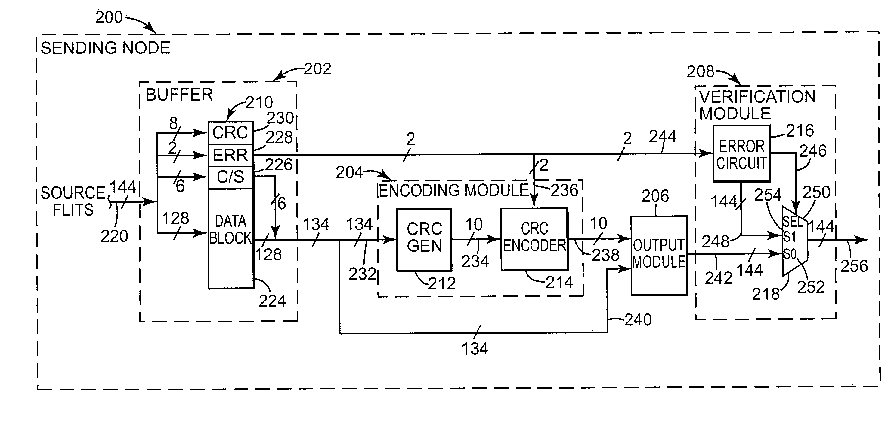
The present invention provides a method for communicating data using a series of data groups with each data group comprising a data block and control / status bits including at least one error status bit having a state indicative of a presence or absence of at least one type of data block error. The method involves generating an expected cyclic redundancy code (CRC) for at least one data group and encoding the expected CRC with the state of the at least one error status bit to generate an encoded CRC. The encoded CRC is then received and compared to an expected CRC for the data group to provide indication of whether a transmission error is present and whether the data block contains corrupt data. The technical effect of this invention is to improve the accuracy and reliability of data communication in networked systems.

Problems solved by technology

CRC bits, however, generally notify a receiving node only of data block errors introduced during transmission via the network connection and do not provide notification of data block errors existing prior to transmission.
For example, a sending node retrieving data from a memory source may detect a presence of an uncorrectable data error in the data retrieved from the memory.
Furthermore, when the errors for which they serve as notification are rarely occurring errors, such as corrupt source data described by the example above, the error and status bits often represent an inefficient use of limited bit capacity.

Method used


Image

  • CRC encoding scheme for conveying status information
  • CRC encoding scheme for conveying status information
  • CRC encoding scheme for conveying status information

Examples


Embodiment Construction

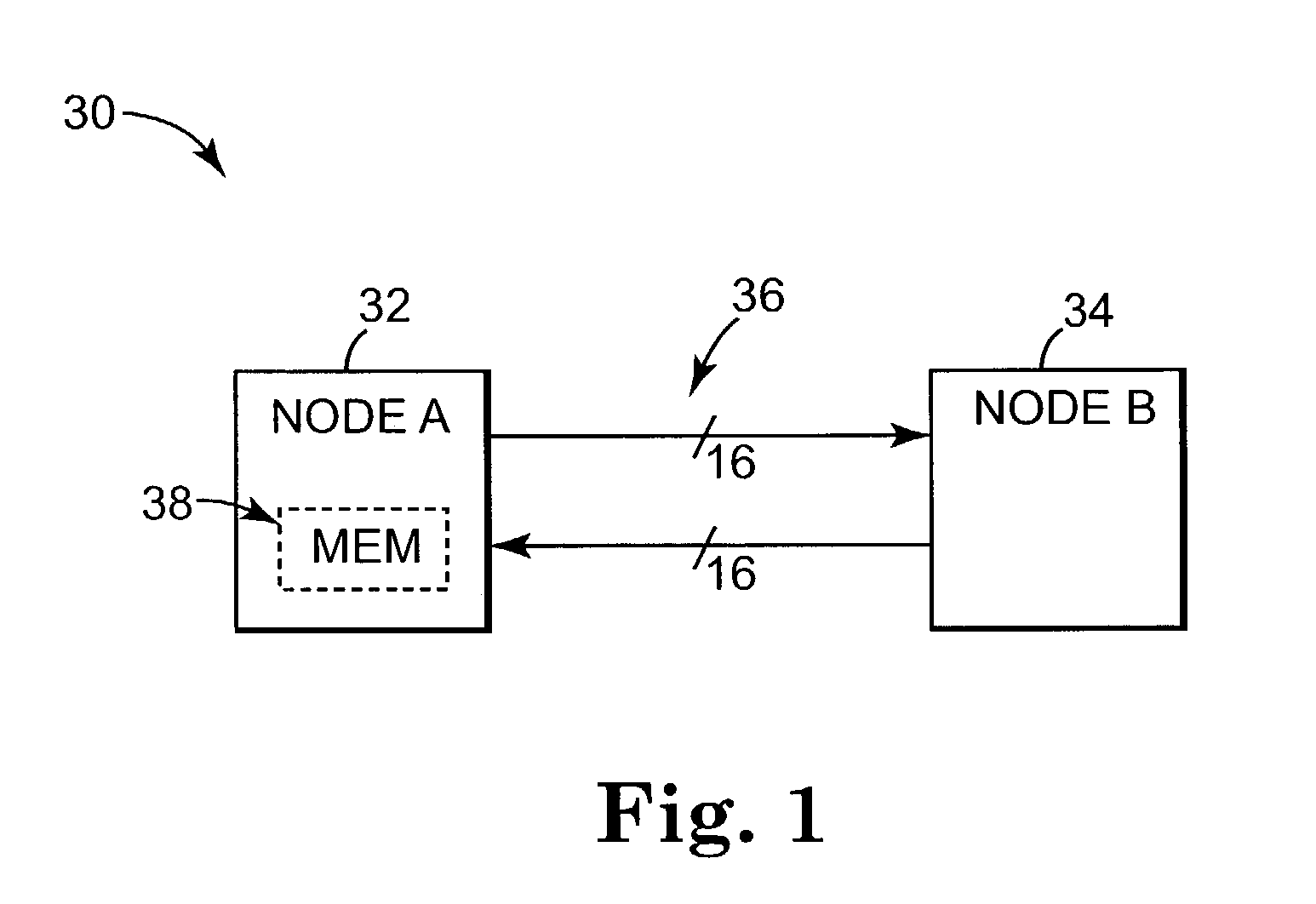
[0018]A networked system is illustrated generally at 30 in block diagram form in FIG. 1. Networked system 30 includes a node A indicated at 32 and a node B indicated at 34. Networked system 30 has the implicit ability to communicate data between node A, 32, and node B, 34, via an interconnect structure, or interconnect link, 36. Interconnect links, however, are often noisy and can introduce “link” errors to the data during its transmission between nodes, such as between nodes A and B. Link errors occurring during transmission are caused by things such as noise, alpha particle hits, and vibrations, and account for a significant portion of errors in networked systems.

[0019]In response to such errors, networked systems typically employ some form of error detection scheme to allow a receiving node, such as node B, 34, to determine whether data received through an interconnect structure was received free of link errors that may have been introduced to the data during transmission. One co...


PUM


Abstract

A sending node of a networked system includes an encoding module configured to receive a series of data groups with each data group comprising a data block comprising data bits, and control / status bits including at least one error status bit having a state indicative of a presence or absence of at least one type of data block error. The sending node is configured to generate for at least one of the data groups of the series an expected cyclic redundancy code (CRC) comprising a plurality of bits that is a function of the data block and control / status bits, not including the at least one error status bit. The sending node is further configured to encode the expected CRC with the state of the at least one error status bit to thereby generate for the at least one data group an encoded CRC comprising a plurality of bits.

Description

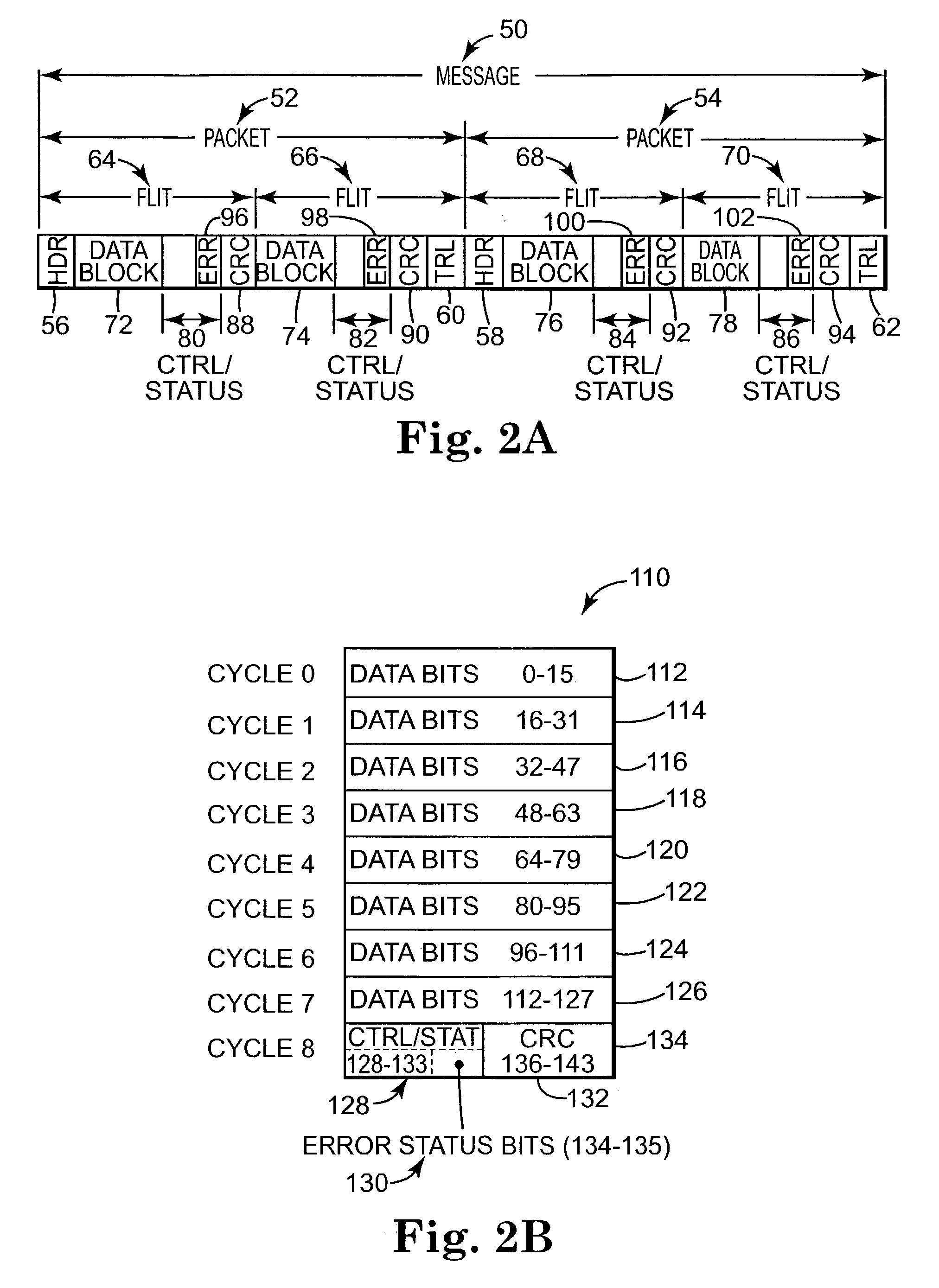
THE FIELD OF THE INVENTION[0001]The present invention relates generally to data communication systems, and more particularly to networked systems transmitting data between distributed nodes and employing error notification and detection techniques to provide notification of whether transmitted data is corrupt or is received free of transmission errors.BACKGROUND OF THE INVENTION[0002]Networked systems generally transmit data between distributed nodes via some form of network connection, which typically comprises some form of physical link. Transmitted data is normally organized into units of data known as packets, with each packet typically consisting of smaller data units known as flits. Each flit, in-turn, generally comprises a data block, control / status bits (such as credits), and cyclic redundancy code (CRC) comprising a plurality of bits. CRC's are utilized by networked systems for transmission error detection. A sending node employs a logical function to calculate the CRC from...

Claims


Application Information

Patent Timeline
Patent Type & Authority Patents(United States)
IPC IPC(8): H03M13/00H04L1/00H04L1/18H03M13/09
CPCH04L1/0061H04L1/1829H04L1/08H04L1/0072
Inventor SHARMA, DEBENDRA DASRAJAMANI, RAMASUBRAMANIAN
Owner HEWLETT-PACKARD ENTERPRISE DEV LP
Learn More