Assembly and method for aircraft engine noise reduction

Inactive Publication Date: 2006-05-23
VIRGINIA TECH INTPROP INC
View PDF14 Cites 41 Cited by
  • Summary
  • Abstract
  • Description
  • Claims
  • Application Information

AI Technical Summary

Benefits of technology

[0020]A method of making an assembly for reducing aircraft engine noise is also described. The method comprises:

Problems solved by technology

Such an array of tubes, if properly located about the engine, creates destructive energy waves that cancel the acoustic energy in the turbofan engine yet do not contribute to any significant aircraft drag or reduced fuel consumption.
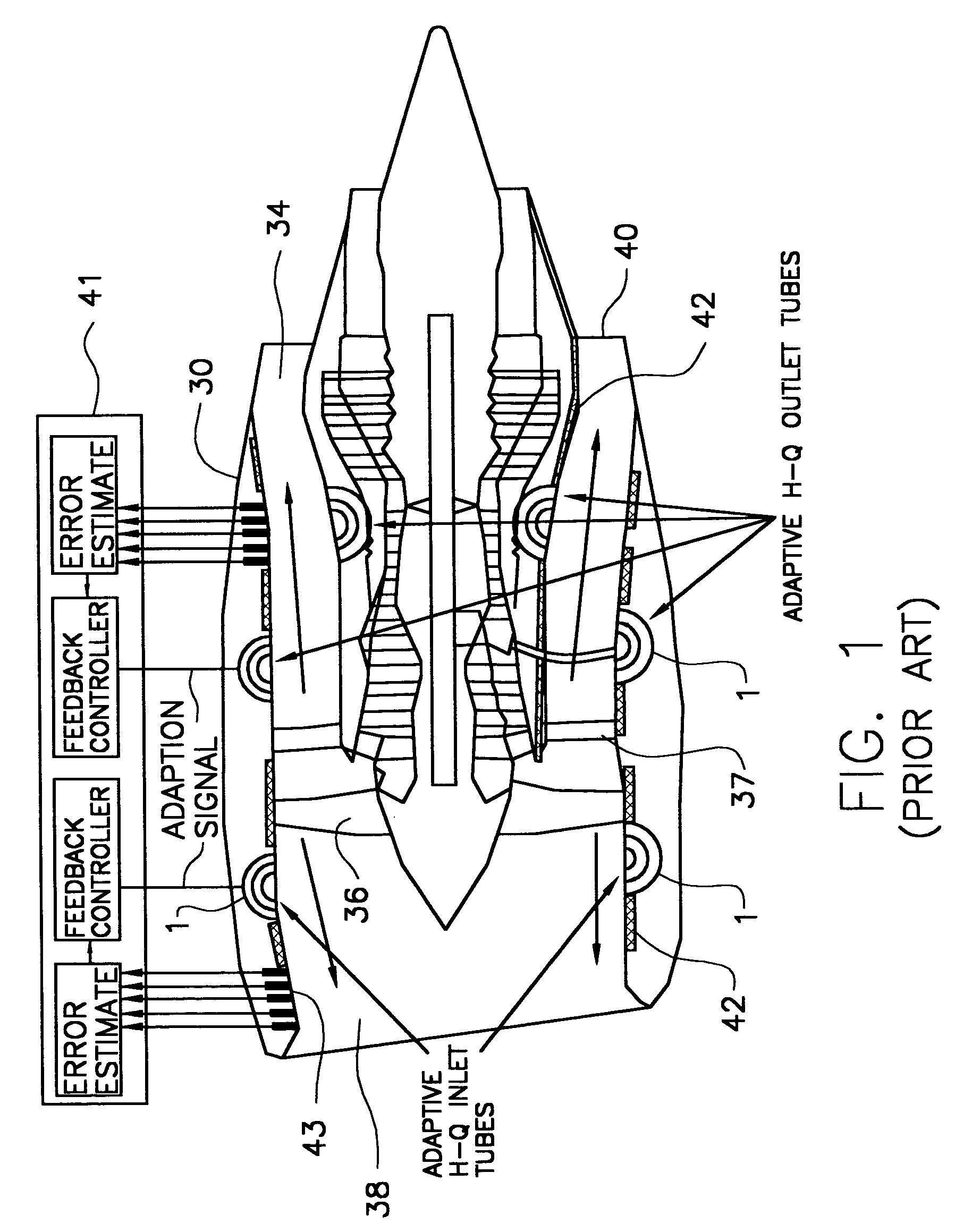
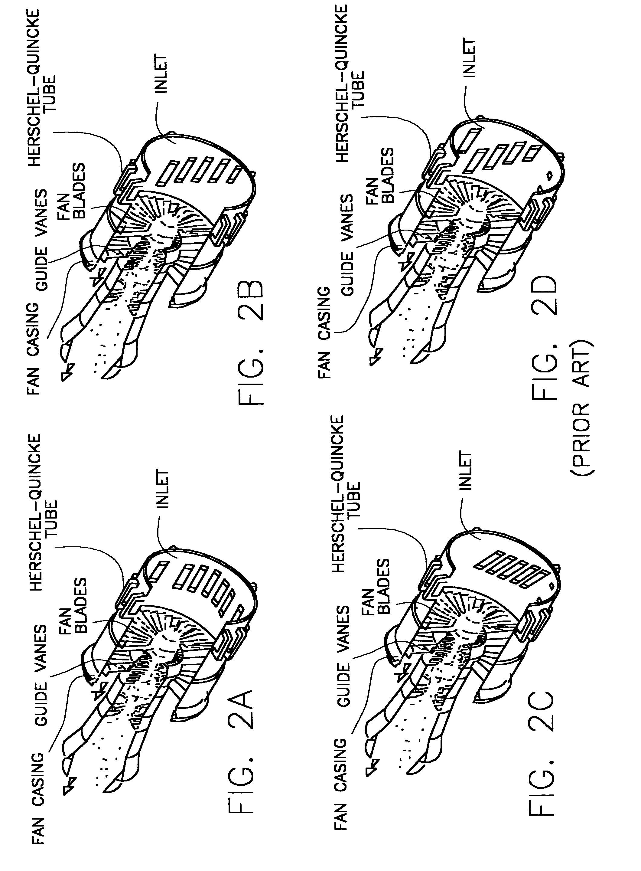
Existing H-Q tube configurations such as those described in U.S. Pat. No. 6,112,514 and WO 02 / 059474 are attached to the external surface of aircraft components, and thus are limited to specific shapes which are not always amenable to integration with the structure of the engine.
In contrast, a prior art external H-Q tube cannot be employed within the core cowl, because the external H-Q tube will physically interfere with other components.
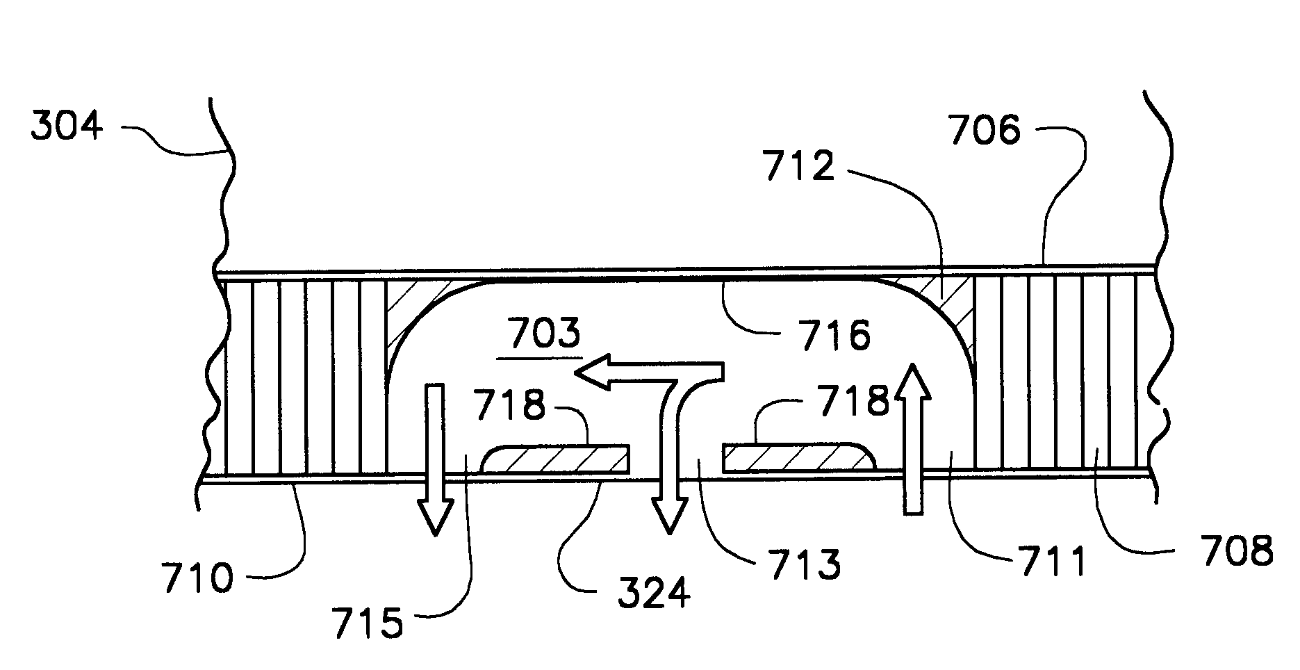
In addition, U.S. Pat. No. 6,112,514 does not disclose the use of a first member having a plurality of openings therein (such as a perforated skin) which is operatively employed with entrance and exit ends of the core portion to permit the passage of acoustic energy into and out of the conduit.

Method used


Image

  • Assembly and method for aircraft engine noise reduction
  • Assembly and method for aircraft engine noise reduction
  • Assembly and method for aircraft engine noise reduction

Examples


Embodiment Construction

[0044]This invention is directed to an assembly, method and system for reducing fan noise from a noise generating system such as a turbofan engine, and to a method of preparing such an assembly. In a preferred embodiment, the assembly, method and system of this invention are used with a turbofan engine. However, other systems such as, for example, systems that generate noise which propagates in a partially enclosed area, such as air ventilation ducts, are equally contemplated for use with the present invention. Accordingly, the assembly, method and apparatus of this invention are not limited to use in conjunction with turbofan engines only, but instead may be used with other noise generating devices or systems. The dimensions of the assembly of this invention, including acoustic energy path length, width, shape and other variables and quantities specified herein may vary depending on the particular application of this invention. Accordingly, numbers and dimensions specified herein a...


PUM


Abstract

An assembly useful in reducing aircraft engine noise such as turbofan engine noise comprises: (a) a core portion comprising at least one entrance end and at least one exit end for the passage of acoustic energy therethrough; (b) a first member having an exterior face and an interior face, wherein the first member is adjacent to at least a part of the core portion, and the first member has a plurality of openings therein to permit the passage of acoustic energy therethrough; and (c) a second member having an exterior face and an interior face, wherein the interior face of the second member is adjacent to the core portion. The core portion may be a honeycomb acoustic structure, and the first member may be perforated to permit the passage of acoustic energy into and out of the conduit portion.

Description

BACKGROUND OF THE INVENTION[0001]1. Field of the Invention[0002]This invention is directed to an assembly, method and system for reducing aircraft noise generated by aircraft engines such as turbofan engines, and to a method of making such an assembly. More particularly, this invention relates to an assembly located in a portion of an aircraft such as a turbofan engine nacelle inlet, engine fan case, core cowl, thrust reverser, core casing, and / or center body. The assembly comprises a core portion having at least one entrance end and at least one exit end for the passage of acoustic energy therethrough. The assembly also comprises a first member having an exterior face and an interior face, wherein the first member is adjacent to at least a portion of the core, and the first member has a plurality of openings therein to permit the passage of acoustic energy therethrough.[0003]2. Background Information[0004]The desirability of reducing the noise generated by aircraft engines such as ...

Claims


Application Information

Patent Timeline
IPC IPC(8): B64F1/26B64D33/00F02C7/045F02K3/02F04D29/66G10K11/16G10K11/172G10K11/175G10K11/178
CPCF02C7/045G10K11/175F05D2250/283F05D2250/191F05D2260/96
Inventor MOE, JEFFREY W.BYRNE, STUART J.JAMES, NORMAN J.BURDISSO, RICARDO A.
Owner VIRGINIA TECH INTPROP INC
Why Eureka
Try Eureka