Micro-electromechanical sensor

a micro-electromechanical and capacitive sensor technology, applied in the direction of fixed capacitor details, fixed capacitors, instruments, etc., can solve the problems of thermal-mechanical mismatch between glass and silicon, inability to achieve the same thermal expansion properties, etc., to achieve the effect of reducing the force range, maximizing the dynamic range, and reducing the sensitivity to force changes

Inactive Publication Date: 2006-05-23
SMC CORP
View PDF29 Cites 20 Cited by
  • Summary
  • Abstract
  • Description
  • Claims
  • Application Information

AI Technical Summary

Benefits of technology

[0008]Unlike conventional capacitive displacement transducers, in which the tension of the resilient element is primarily determined by the dimensions of the resilient element, the tension of the resilient element of the present invention is secondarily determined by the dimensions of the resilient element and is primarily determined by the height of the spacing member. The dimensions of the resilient element and, to an even greater degree, the height of the spacing member can be finely controlled and reproduced using MEMS and other semi-conductor device fabrication processes and techniques. Therefore, the accuracy and precision of the pressure transducer of the present embodiment are dramatically improved over those of conventional pressure transducers.
[0010]In one embodiment of the present invention, the spacing member may be positioned approximately at the center of the resilient element. In this embodiment, the central portion of the resilient element is separated from the dielectric material by the spacing member, and a peripheral portion of the resilient element is in contact with the dielectric material. According to the present invention, a transducer having this configuration has a higher sensitivity to force changes at lower force ranges. In the present invention, the transducer configuration preferably exhibits a log-linear sensitivity to applied force, which can maximize dynamic range.

Problems solved by technology

Based upon the application, transducers can range from inexpensive to very expensive, depending on the precision, accuracy, sensitivity, and reliability required.
One problem associated with such conventional transducer structures is thermal-mechanical mismatch between glass and silicon.
Glass and silicon, however, do not have identical thermal expansion properties, and their differences can significantly affect the tension of the diaphragm.
Tension in the diaphragm also varies from transducer to transducer, as it is difficult to precisely recreate the same tension in the diaphragms.
The largest inaccuracy in conventional pressure transducers is composed of common-mode or absolute errors, the sources of which are independent of pressure.
However, many applications require a transducer with great accuracy at the low end of the pressure range.
However, the art has failed to provide a micro-sensor that is relatively reproducible and cost effective to manufacture, while exhibiting the low range accuracy of relative error device.

Method used


Image

  • Micro-electromechanical sensor
  • Micro-electromechanical sensor
  • Micro-electromechanical sensor

Examples


Embodiment Construction

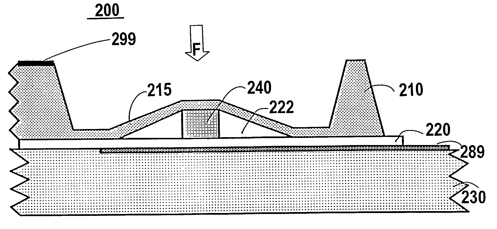
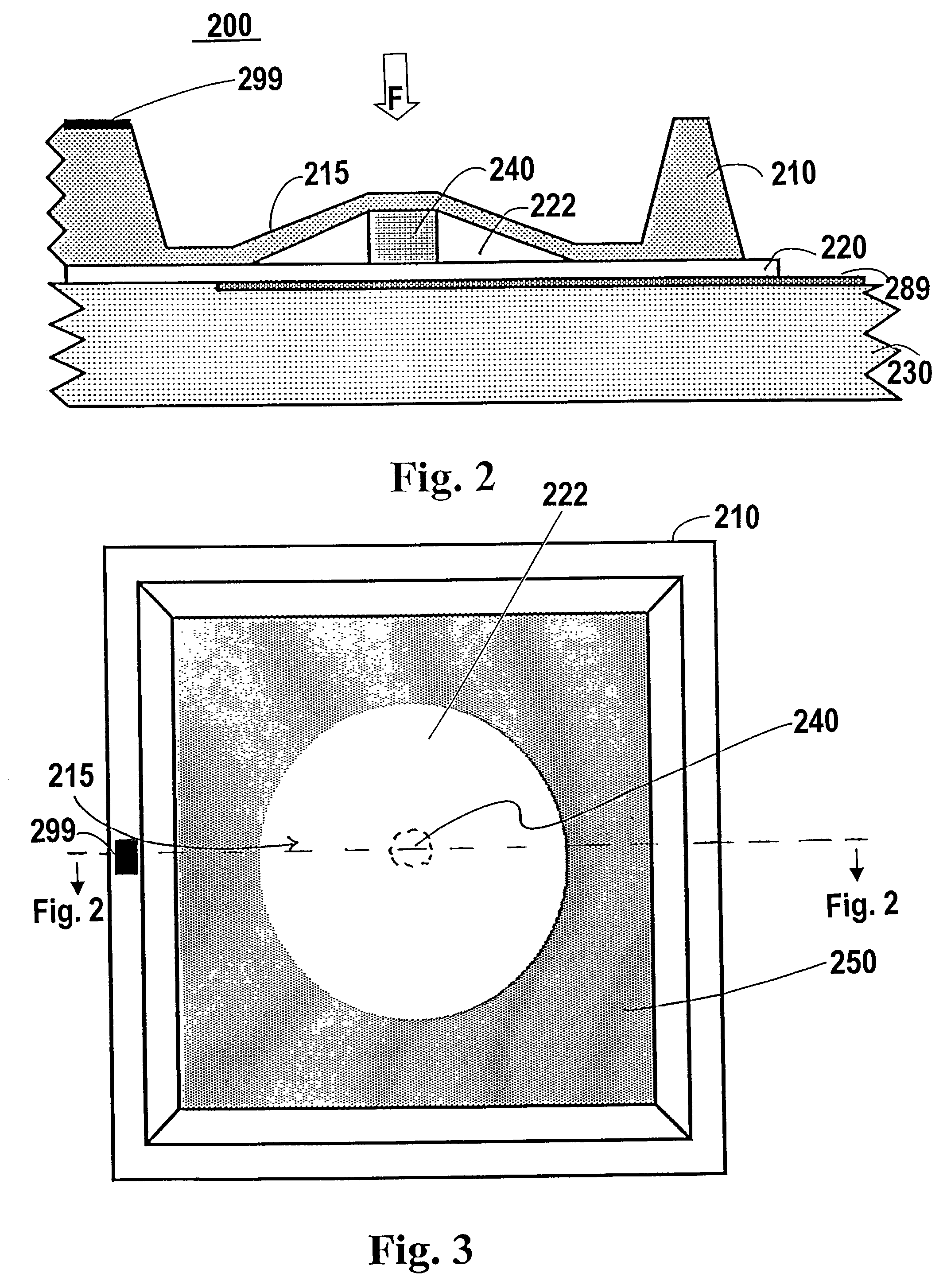
[0043]As shown in FIG. 2, transducer 200 according to an embodiment of the present invention comprises substrate 230, a dielectric 220 (which may be disposed on the substrate 230), spacing member 240, and resilient stratum 210 disposed over the dielectric 220. In the illustrated embodiment, substrate 230 includes an optional conductive layer 289 that acts as an electrode of the capacitor. The resilient stratum 210 includes a diaphragm portion 215 that is configured to act as another electrode of the capacitor. The diaphragm portion 215 is at least partially separated from the dielectric 220 by spacing member 240. As shown in FIG. 2, dielectric 220 comprises a layer of a dialectic material, which may be selected by a person skilled in the art from know dielectric materials. Alternatively, dielectric 220 may be configured as a vacuum layer. Void 222, which is created by spacing member 240 between diaphragm portion 215 and dielectric 220, may be evacuated or may contain a displaceable ...


PUM

PropertyMeasurementUnit
diameteraaaaaaaaaa
diameteraaaaaaaaaa
diameteraaaaaaaaaa

Abstract

A force or pressure transducer is disclosed. In one embodiment, the transducer has a substrate, a dielectric material disposed on the substrate, a spacing member disposed on the dielectric material, and a resilient element disposed on the dielectric material and the spacing member. A portion of the resilient element is separated from the dielectric material, and a portion of the resilient element is in contact with the dielectric material. The contact area between the resilient element and the dielectric material varies in response to movement of the resilient element. Changes in the contact area alter the capacitance of the transducer, which can be measured by circuit means.

Description

[0001]The present application claims priority under 35 U.S.C. §119 to U.S. provisional patent application bearing Ser. No. 60 / 306,175 filed Jul. 17, 2001.FIELD OF THE INVENTION[0002]The present invention relates generally to the field of micro-electromechanical systems (MEMS). More specifically, the present invention relates to micro-electromechanical variable capacitive sensors.BACKGROUND OF THE INVENTION[0003]Transducers are generally devices that convert an input of one form of energy into an output of another form of energy. Many types of transducers are available for converting light to electrical signals, mechanical energy to electrical signals, temperature to pressure, pressure to electrical signals, acceleration to electrical signals, electrical signals to motions, etc., and vice versa. Equipment or apparatus that operates between different types of energy generally requires one type of transducer or another. Based upon the application, transducers can range from inexpensive...

Claims


Application Information

Patent Timeline
Patent Type & Authority Patents(United States)
IPC IPC(8): G01L9/12G01L1/14G01L9/00H01G5/18H01L29/84
CPCG01L9/0073G01L1/148
Inventor ZIAS, ARTMAUGER, PHILCAHILL, SEANNYSTROM, NORMHENNING, ALBERT K.
Owner SMC CORP
Why Eureka
Try Eureka