Valve-driving system of internal combustion engine and valve-driving apparatus

a technology of internal combustion engine and valve drive, which is applied in the direction of machines/engines, non-mechanical valves, output power, etc., can solve problems such as unsuitability, and achieve the effect of enhancing flexibility in the operation characteristics of each valve and efficient opening and closing of intake valves

Inactive Publication Date: 2006-05-23
TOYOTA JIDOSHA KK
View PDF18 Cites 13 Cited by
  • Summary
  • Abstract
  • Description
  • Claims
  • Application Information

AI Technical Summary

Benefits of technology

[0007]It is an object of the present invention to provide a valve-driving system which is applied to an internal combustion engine having a plurality of cylinders and which is capable of efficiently opening and closing intake valves or exhaust valves ther

Problems solved by technology

Since the apparatus which converts rotation of a motor into opening and closing motion of a valve by means of the screw mechanism is such that a necessary amount of rotation of the mot

Method used


Image

  • Valve-driving system of internal combustion engine and valve-driving apparatus
  • Valve-driving system of internal combustion engine and valve-driving apparatus
  • Valve-driving system of internal combustion engine and valve-driving apparatus

Examples


first embodiment

[0050][First Embodiment]

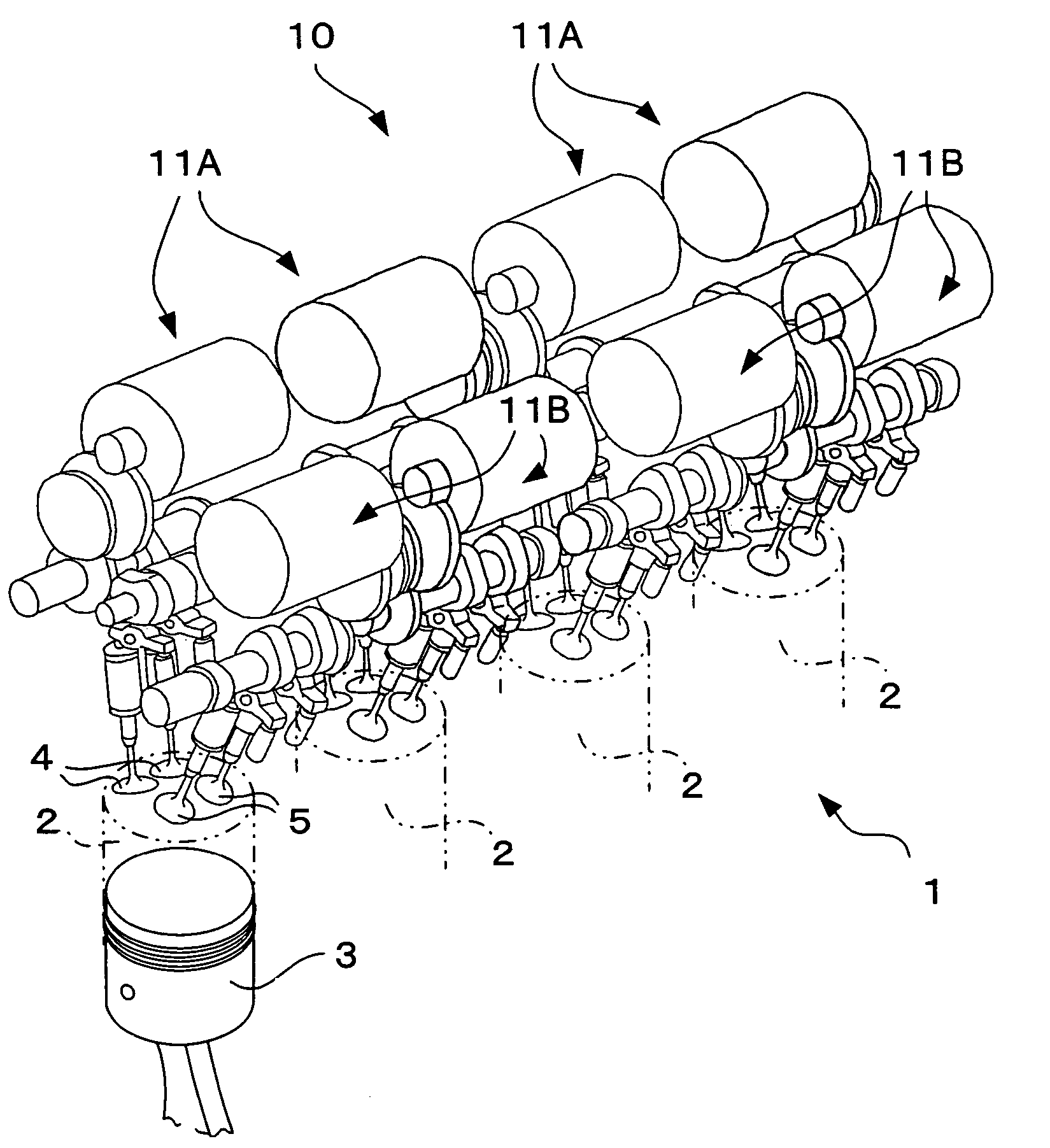
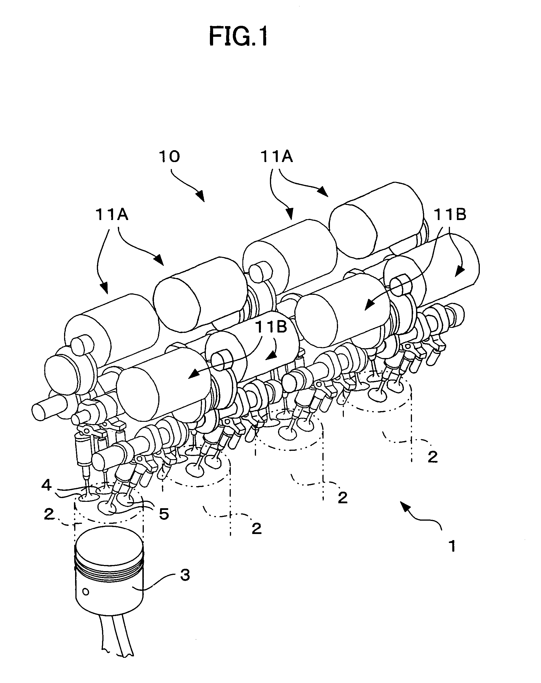
[0051]FIG. 1 shows an internal combustion engine 1 in which a valve-driving system according to the first embodiment of the present invention is incorporated. The internal combustion engine 1 is a multi-cylinder in-line gasoline engine. In the engine, a plurality of (four in FIG. 1) cylinders 2 . . . 2 are arranged in one direction, and pistons 3 are mounted in the respective cylinders 2 such that the pistons 3 can move vertically. Two intake valves 4 and two exhaust valves 5 are provided above each cylinder 2. These intake valves 4 and exhaust valves 5 are opened and closed by a valve-driving system 10 in association with vertical motion of the piston 3, thereby drawing air into the cylinder 2 and exhausting air from the cylinder 2.

[0052]The valve-driving system 10 includes valve-driving apparatuses 11A . . . 11A provided on an intake-side of each cylinder 2 one each, and valve-driving apparatuses 11B . . . 11B provided on an exhaust-side of each cylinder 2 ...

second embodiment

[0101][Second Embodiment]

[0102]A second embodiment of the present invention will be explained. In the first embodiment, the cam friction torque is estimated and the output torque of the motor 12 is controlled. In the second embodiment, the variation in the revolution number (rotation speed) of the internal combustion engine 1 is estimated based on the operation state of the internal combustion engine 1, and the output torque of the motor 12 is controlled in accordance with the result of the estimation. The mechanical structures of the valve-driving apparatuses 11A and 11B are the same as those in the first embodiment.

[0103]FIG. 15 is a block diagram of a control system mounted in the motor control apparatus 40 of the second embodiment of the present invention. This structure may be realized by a combination between a CPU and software or by a hardware circuit. In this embodiment, a required cam angle as a control target value is calculated based on the crank angle detected by the cra...

third embodiment

[0110][Third Embodiment]

[0111]Next, a third embodiment of the present invention will be explained. In this embodiment, the driving modes of the motors 12 of the valve-driving apparatuses 11A and 11B are switched between a normal rotation mode and a normal-reverse rotation mode in accordance with the operation state of the internal combustion engine 1. The normal rotation mode is a mode in which the motor 12 is continuously rotated in a constant direction (normal direction), and the normal-reverse rotation mode is a mode in which the rotation direction of the motor 12 is switched appropriately between the normal rotation direction and the reverse rotation direction. The mechanical structures of the valve-driving apparatuses 11A and 11B are the same as those in the first embodiment.

[0112]FIG. 18 shows one example of switching conditions concerning the driving mode of the motor 12. In this example, the motor driving mode is switched based on the revolution number and a load of the inte...


PUM


Abstract

A valve-driving system, which is applied to an internal combustion engine having a plurality of cylinders, for driving an intake or exhaust valve provided in each cylinder, comprising: a plurality of valve-driving apparatuses, each of which is provided for at least each one of the intake valve and the exhaust valve, each valve-driving apparatus having an electrical motor as a driving source for generating rotation motion and a power transmission mechanism provided with a transmitting section for transmitting the rotation motion generated by the electrical motor and a converting section for converting the rotation motion transmitted from the transmitting section into opening and closing motion of the valve to be driven; and a motor control device which controls operations of electric motors of the respective valve-driving apparatuses in accordance with the operation state of the internal combustion engine.

Description

BACKGROUND OF THE INVENTION[0001]1. Field of the Invention[0002]The present invention relates to a valve-driving system for driving intake or exhaust valves of an internal combustion engine, and also to a valve-driving apparatus which constitutes the valve-driving system.[0003]2. Description of the Related Art[0004]An intake valve or an exhaust valve of a conventional internal combustion engine is opened and closed by power taken out from a crank shaft of an internal combustion engine. In recent years, however, an attempt has been made to drive the intake valve or the exhaust valve by means of an electric motor. For example, Japanese Patent Application Laid-open No. 8-177536 discloses a valve-driving apparatus which drives a cam shaft by a motor to open and close the intake valve, and for driving an EGR valve, there is also known a valve-driving apparatus which converts rotation of a motor into a straight opening and closing motion of the valve utilizing a screw mechanism provided o...

Claims


Application Information

Patent Timeline
IPC IPC(8): F01L1/34F01L1/32F01L9/20F01L9/22F01L13/00F02D13/02
CPCF01L1/32F01L9/04F01L13/00F01L13/0015F01L1/34F01L2201/00F01L2800/00F01L2009/0411F01L9/22F01L9/20F02D13/02
Inventor ASADA, TOSHIAKIEZAKI, SHUICHITSUJI, KIMITOSHIKUSAKA, YASUSHIKATAOKA, KENJI
Owner TOYOTA JIDOSHA KK
Why Eureka
Try Eureka