Driver's cab for a work vehicle

a technology for work vehicles and drivers, applied in the direction of roofs, transportation and packaging, tractors, etc., can solve the problems of large deformation of the ceiling portion, countermeasures that cannot achieve the structure which is prepared, and the vehicle body inverts, so as to prevent local bending deformation, prevent deformation, and strengthen the driver's cab

Active Publication Date: 2006-05-23
KOMATSU LTD
View PDF23 Cites 42 Cited by
  • Summary
  • Abstract
  • Description
  • Claims
  • Application Information

AI Technical Summary

Benefits of technology

[0010]The present invention is made for the purpose of solving the problems mentioned above, and an object of the present invention is to provide a driver's cab for a work vehicle which is provided with a function of effectively transferring an external force applied to a ceiling portion to a pillar without making a structure complex, and can achieve a reinforced structure.

Problems solved by technology

However, in the work in the construction field having a bad false work such as the work in a slope ground in the case of the excavator, there is a risk that a vehicle body inverts.
However, since both of the prior arts mentioned above correspond to a strengthening countermeasure which attaches importance to a cross sectional structure of the pillar portion, the countermeasure does not achieve a structure which is prepared for the case that an external force is applied to a ceiling portion of the driver's cab from an external portion, for example, from a side surface portion and the case that the external force is applied from a rear side of the ceiling portion.
In accordance with the matter mentioned above, for example, when the great external force is applied to a middle position of the ceiling portion in a longitudinal direction of the driver's cab, the external force is not transmitted well to the pillar at the middle position, so that there is a risk the ceiling portion is largely deformed.
Further, when there is generated a matter that the external force is applied to a rear portion of the ceiling of the driver's cab, there is a risk that the ceiling is pressed down to an inner side, in view of the structure which is not prepared for the external force.
In any case, because of intending a weight saving of the vehicle body and giving a priority to an improvement of visibility at the time of driving, it is absolutely insufficient to transmit the external force to the pillar in the case that the external force is applied to the ceiling portion due to the inverting load, and it is unavoidable that the deformation of the driver's cab becomes large accompanying therewith.
In other words, a risk of the operator is great.

Method used


Image

  • Driver's cab for a work vehicle
  • Driver's cab for a work vehicle
  • Driver's cab for a work vehicle

Examples


first embodiment

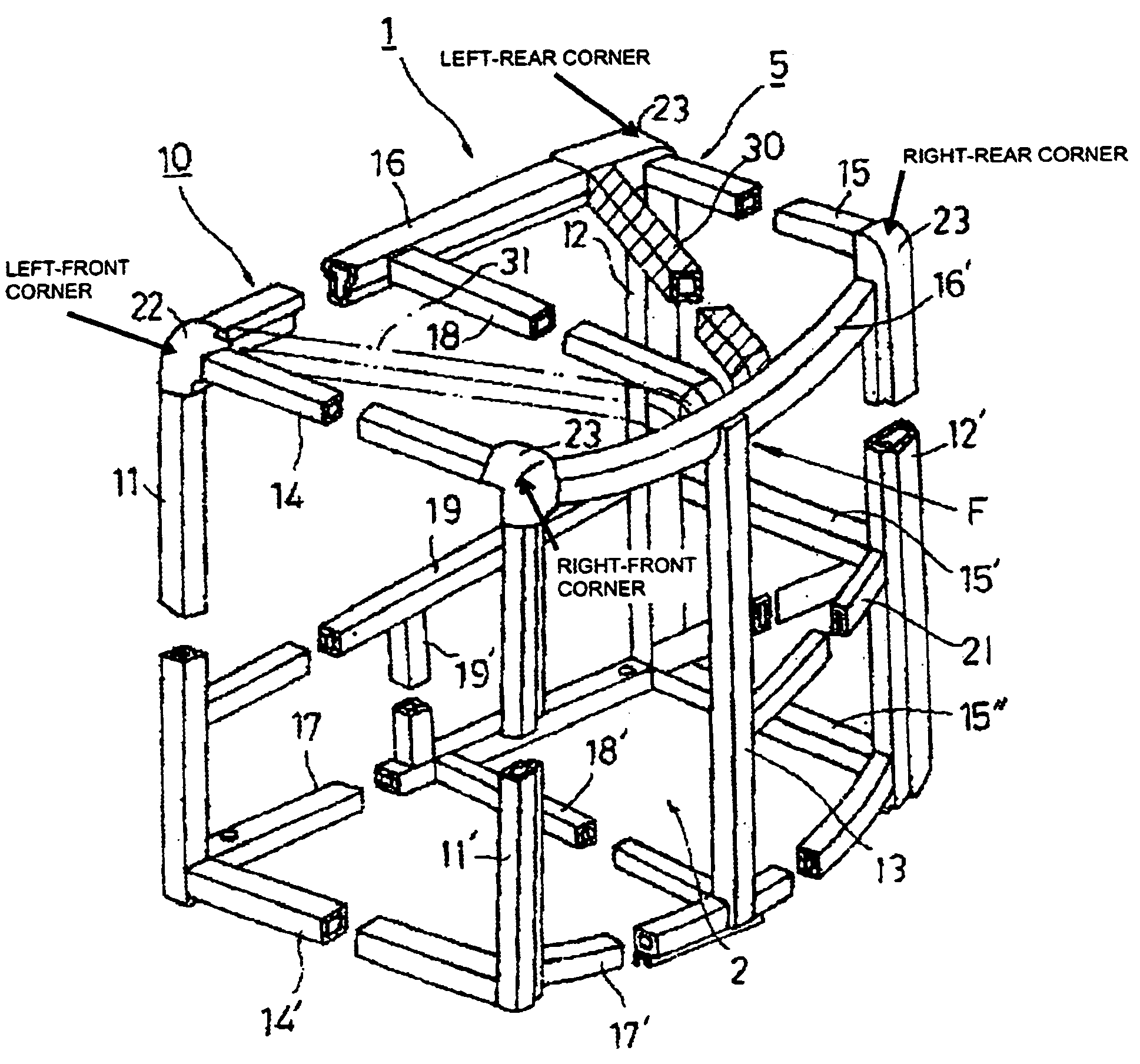
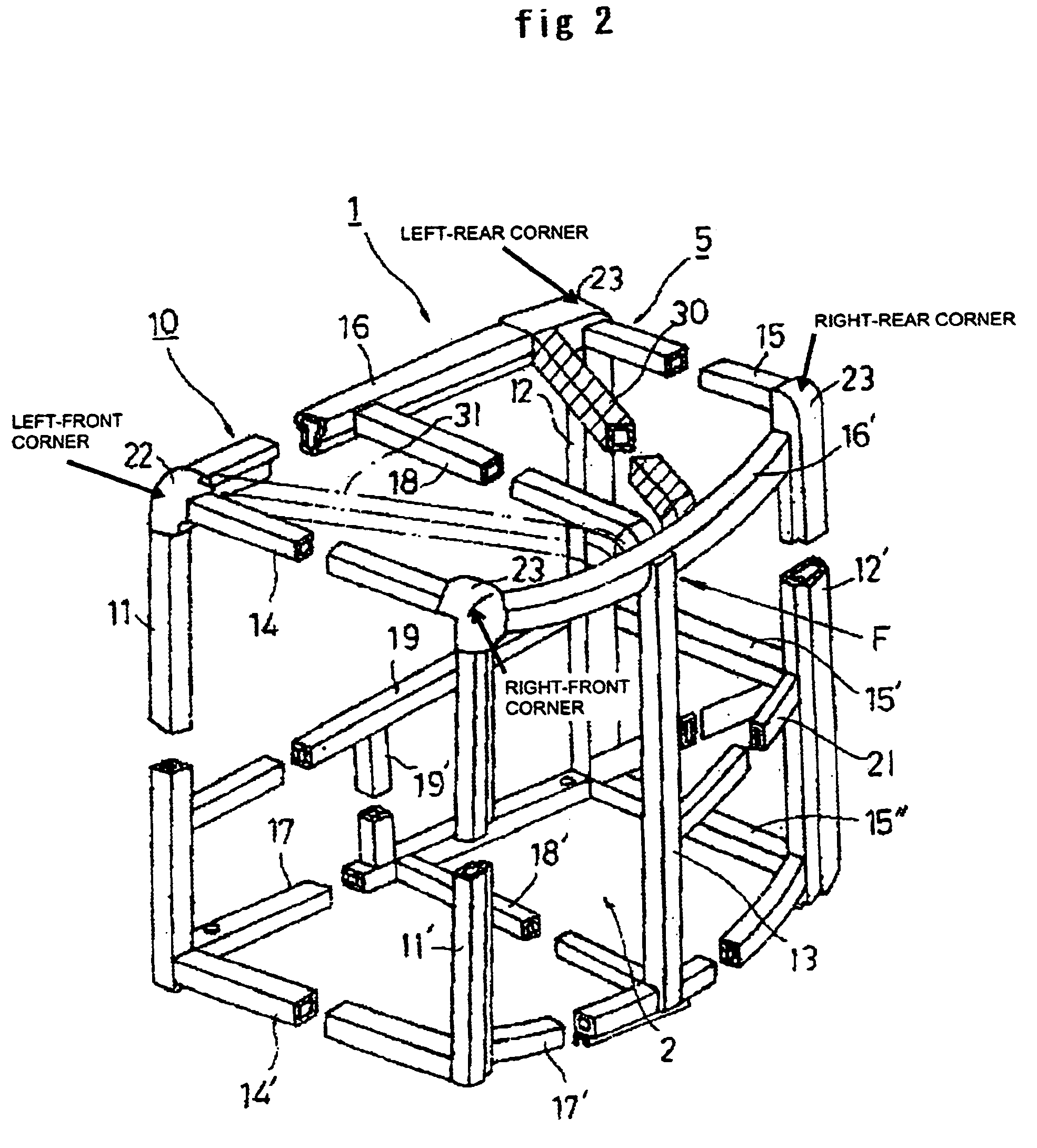
[0032]Then, in accordance with a first embodiment, a connection member 30 which is shown by adding diagonal lines in FIG. 2 is arranged so as to connect between a middle position of the ceiling portion 5 (a middle position of the longitudinal member 16) and a top portion of the left support pillar 12 in the rear portion or a portion close thereto. In this case, the connection member 30 is formed by a pipe member in the same manner as that of the members in the other portions.

[0033]By arranging the connection member 30 diagonally in the manner mentioned above, even when there is generated a matter that the external force F as mentioned above is applied to a side portion of the ceiling portion 5, the external force is not transmitted to the support pillar 12 via the longitudinal member 16 but is transmitted to the support pillar 12 immediately through the connection member 30, which is different from the conventional manner, so that it is possible to prevent the deformation.

second embodiment

[0034]In accordance with a second embodiment, as the framework of the ceiling portion in the driver's cab frame is shown in FIG. 3 by using the schematic view, in the framework structuring the ceiling portion 5 in the frame 10 mentioned above, connection members 30 and 31 are diagonally arranged and connected between a position of the middle portion in the outer longitudinal member 16′ and respective upper end portions of the front support pillar 11 and the rear support pillar 12 connected to the longitudinal member 16 in the opposite side or portions close thereto.

[0035]In accordance with the structure mentioned above, even when the external force is applied to the middle position of the outer longitudinal member 16′ in the same manner as mentioned above, the external force is immediately transmitted to the front and rear support pillars 11 and 12 by both of the diagonal connection members 30 and 31 and can be set against by the stresses thereof, so that it is possible to prevent t...

third embodiment

[0036]A third embodiment is structured, as shown by a schematic view showing the framework of the ceiling portion in the driver's cab frame in FIG. 4, such that the diagonal connection member 30 is connected between the middle position of the outer longitudinal member 16′ in the ceiling portion 5 and the upper end portion of the rear support pillar 12 connected to the longitudinal member 16 in the opposite side or the portion close thereto, and another short connection member 32 connects between the diagonal connection member 30 and a middle portion of the transverse member 15 in the rear portion. In accordance with the structure mentioned above, the same matter as mentioned above is applied in the case that the external force is applied to the outer side portions, and further, since the force transmission to the rear support pillar 12 can be effectively carried out via the diagonal connection member 30 even in the case that the external force is applied to the ceiling rear portion ...


PUM


Abstract

The invention provides a driver's cab for a work vehicle which is provided with a function of effectively transferring an external force applied to a ceiling portion to a pillar without making a structure complex, and can achieve a reinforced structure. In a driver's cab (1) in a working vehicle, the driver's cab being structured by a pipe-like member, a connection member (30 (31)) for dispersing a stress is arranged in a support pillar (11 (12)) in an opposite side particularly in the case that an external force is applied to a transverse outer side of a ceiling portion.

Description

BACKGROUND OF THE INVENTION[0001]1. Field of the Invention[0002]The present invention relates to a driver's cab for a work vehicle such as a construction machine including a excavator, a farm machine including a tractor, and other industrial machines.[0003]2. Description of the Background Art[0004]The work vehicle includes various kinds such as the construction machine, the farm machine, cargo handling machine, and other such machines however, for example, the excavator in the construction machine is widely used for a civil engineering work accompanying with a segment excavation, a construction foundation work, a building dismantling work or the like. In these works, an operator operates and handles the working machine while seeing forward mainly through a front window from an inner side of the driver's cab. For the driver's cab of the work vehicle in which the work is carried out while seeing mainly forward from the inner side of the driver's cab as mentioned above, it is most desi...

Claims


Application Information

Patent Timeline
Patent Type & Authority Patents(United States)
IPC IPC(8): B62D33/06B62D23/00E02F9/16B62D25/08B62D33/04
CPCB62D23/005B62D33/06B62D33/044
Inventor MORI, TADASHITSUJI, KOUDOUITOU, TATSUSHI
Owner KOMATSU LTD
Why Eureka
Try Eureka