Air bag starter and backup circuit used therein

a backup circuit and air bag technology, applied in the direction of process control, process and machine control, pedestrian/occupant safety arrangement, etc., can solve the problems of reducing operation reliability, reducing operation reliability, and unstable waveform of mechanical acceleration switch b>12/b>, so as to ensure operation reliability. the effect of igniting operation

Inactive Publication Date: 2006-05-23
MITSUBISHI ELECTRIC CORP
View PDF6 Cites 3 Cited by
  • Summary
  • Abstract
  • Description
  • Claims
  • Application Information

AI Technical Summary

Benefits of technology

[0026]The present invention has been made to solve the above-discussed problems and has an object of providing an air bag starter in which an ignition current

Problems solved by technology

However, a collision involving a vehicle includes extremely indefinite factors, and therefore an operation waveform of the mechanical acceleration switch 12 is not always stable, contrary to the waveform illustrated in FIG. 6. FIG. 7 is a timing explanation diagram for explaining a timing and shows a waveform that is more likely to actually occur.
As a result, a first-stage ignition current delivered from the condenser 11 to the air bag 3 or 6 has a waveform that oscillat

Method used


Image

  • Air bag starter and backup circuit used therein
  • Air bag starter and backup circuit used therein
  • Air bag starter and backup circuit used therein

Examples


embodiment 1

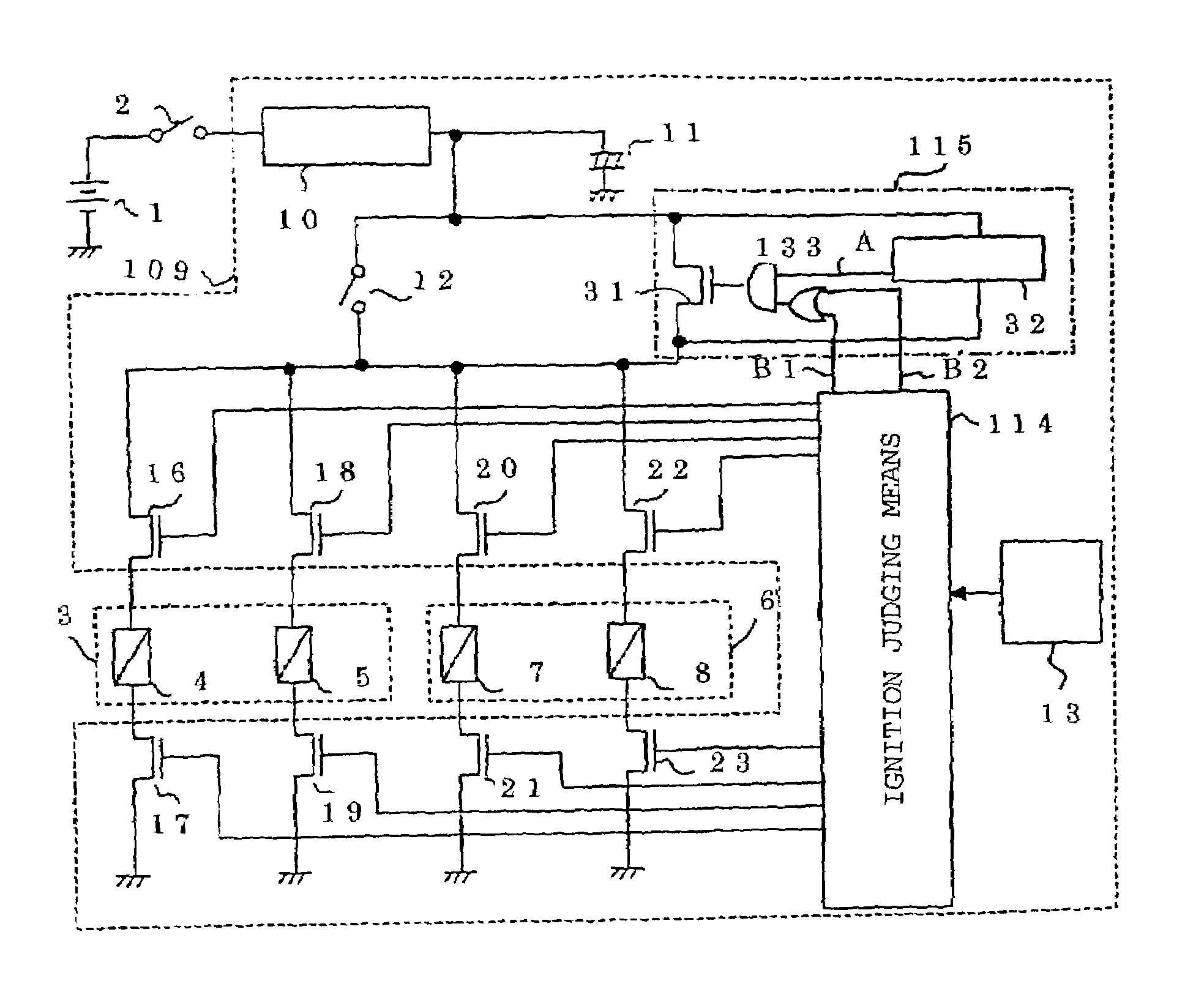
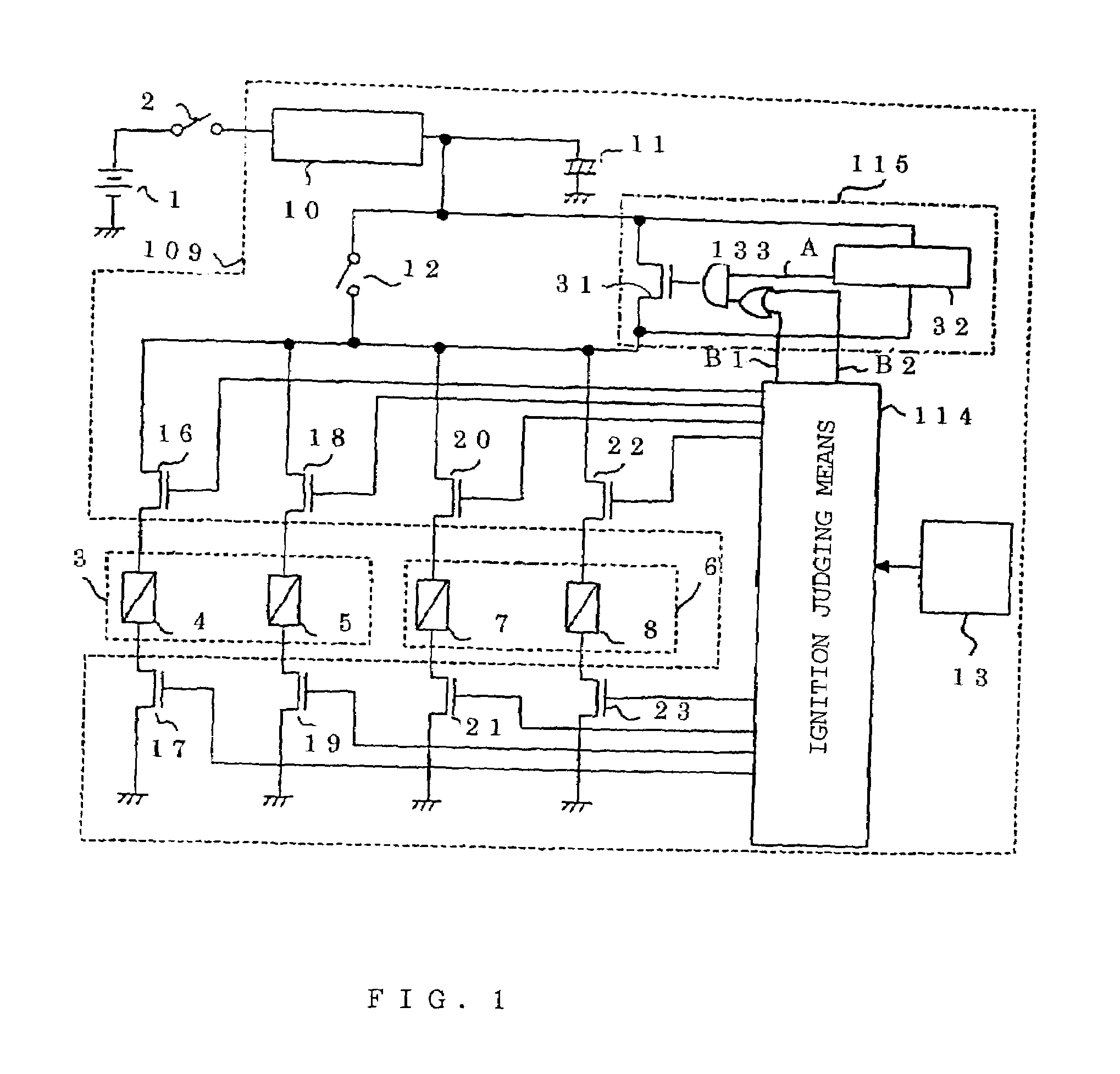
[0037]FIG. 1 is a circuit diagram of an air bag starter according to Embodiment 1, in which a two-stage ignition type air bag system is taken as an example. In the drawings, the same numerals indicate same parts as those in the drawings used to explain the conventional air bag starter, and a detailed explanation of them is, thus, not repeated.

[0038]Now referring to the drawings, reference numeral 1 is a battery installed in a vehicle, and numeral 2 is an ignition switch for starting an engine of the vehicle. Numeral 3 is a driver's seat air bag disposed in the driver's seat, and numeral 4 is an igniter (e.g., detonating primer) for a first-stage inflator (e.g., detonating powder or the like, though not shown in the drawing) used to inflate the driver's seat air bag 3. Numeral 5 is an igniter for a second-stage inflator that is ignited, when required, synchronously with the first-stage inflator or after a predetermined delay following the ignition of the first-stage inflator.

[0039]Nu...

embodiment 2

[0053]Now, a case of a one-stage ignition type air bag system is hereinafter described with reference to FIG. 3. The fundamental constitution is the same as that in FIG. 1 and, thus, any further detailed explanation is unnecessary. Air bags 3 and 6 are not provided with any second-stage igniter and, consequently, no driving transistors to be connected to such a second-stage igniter exist. The forced igniting means 115 is provided with an AND gate 33 that acts upon receipt of the signal A outputted by the closure detecting means 32 and the signal B outputted by the ignition judging means 114.

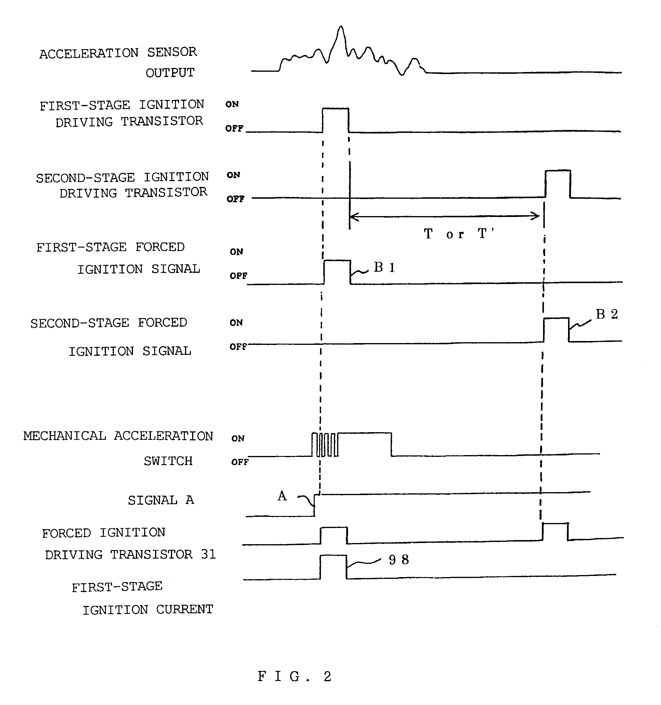
[0054]Operation of the air bag starter in FIG. 3 is hereinafter described with reference to a timing chart of FIG. 4.

[0055]Upon occurrence of a collision involving the vehicle, during the period when acceleration caused by the collision exceeds a predetermined acceleration level, the mechanical acceleration switch 12 is closed and chattering may occur. At this time, the closure detecting means 32...

embodiment 3

[0058]In the foregoing Embodiments 1 and 2, an air bag starter to be connected to the air bags is specifically described in detail. However, it is to be noted that the most essential part of the invention is a backup circuit. This backup circuit is arranged to back up the mechanical acceleration switch 12 and avoid the negative influence of the chattering thereon by turning on the transistor 31 connected in parallel to a contact of the mechanical acceleration switch 12 when a detection signal of the acceleration sensor 13 disposed separately from the mechanical acceleration switch 12 exceeds a predetermined level.

[0059]Specifically, the backup circuit is constituted as a device including the forced igniting means 115, the ignition judging means 114, and the acceleration sensor 13 in FIG. 1, for example. Therefore, the same advantage is achieved even in a case of constituting, for example, the backup circuit alone. In such a constitution, the DC-to-DC converter 10, the condenser 11, ...


PUM


Abstract

A mechanical acceleration switch acting in response to a collision involving a vehicle tends to occur with chattering, thereby lowering the reliability of operation due to insufficient application of an ignition current to an igniter of an air bag in the vehicle. When the mechanical acceleration switch is closed and first-stage igniters are ignited, a forced igniter is turned on. Even if chattering occurs in the mechanical acceleration switch, the first-stage igniters and a backup capacitor are conductively connected by turning on a driving transistor, such that an electric current is sufficiently delivered to the igniters. As a result, it is possible to improve the reliability of the operation of starting the air bag. Furthermore, it is no longer necessary to increase a capacity of the capacitor and change the constitution of the mechanical acceleration switch to decrease chattering therewith.

Description

BACKGROUND OF THE INVENTION[0001]1. Field of the Invention[0002]The present invention relates to an air bag starter that is installed in a vehicle and protects a driver and a passenger inside the vehicle from a shock at the time an accident, such as collision, occurs and to a backup circuit that is used in the air bag starter to accurately back up an inflating operation of the air bag.[0003]2. Description of Related Art[0004]A so-called air bag system that is installed in a vehicle (e.g., a car) and inflated by, for example, igniting a powder loaded in the system or breaking a plug (stopper) of a high-pressure cylinder upon occurrence of a collision or the like, in order to protect a driver and a passenger inside the vehicle from a shock, has been put into practical use. A system for ignition of the air bag including an electric circuit is hereinafter referred to as an air bag starter or simply a starter.[0005]FIG. 5 shows an example of a construction of a conventional starter, for ...

Claims


Application Information

Patent Timeline
IPC IPC(8): B60R21/16B60R21/01B60R21/00B60R21/017
CPCB60R21/017B60R21/0176
Inventor HANAZAKI, YASUMASAFURUI, TAKASHI
Owner MITSUBISHI ELECTRIC CORP
Why Eureka
Try Eureka