
Projection display systems utilizing color scrolling and light emitting diodes

a technology of color scrolling and projection display, which is applied in the field of projection display systems, can solve the problems of low luminance of leds, inability to produce optical output images whose luminance is higher, and frequent mismeasurement, and achieve the effect of maximising the intrinsic source luminan

Inactive Publication Date: 2006-05-23
GOLDENEYE
View PDF13 Cites 134 Cited by
  • Summary
  • Abstract
  • Description
  • Claims
  • Application Information

AI Technical Summary

Benefits of technology

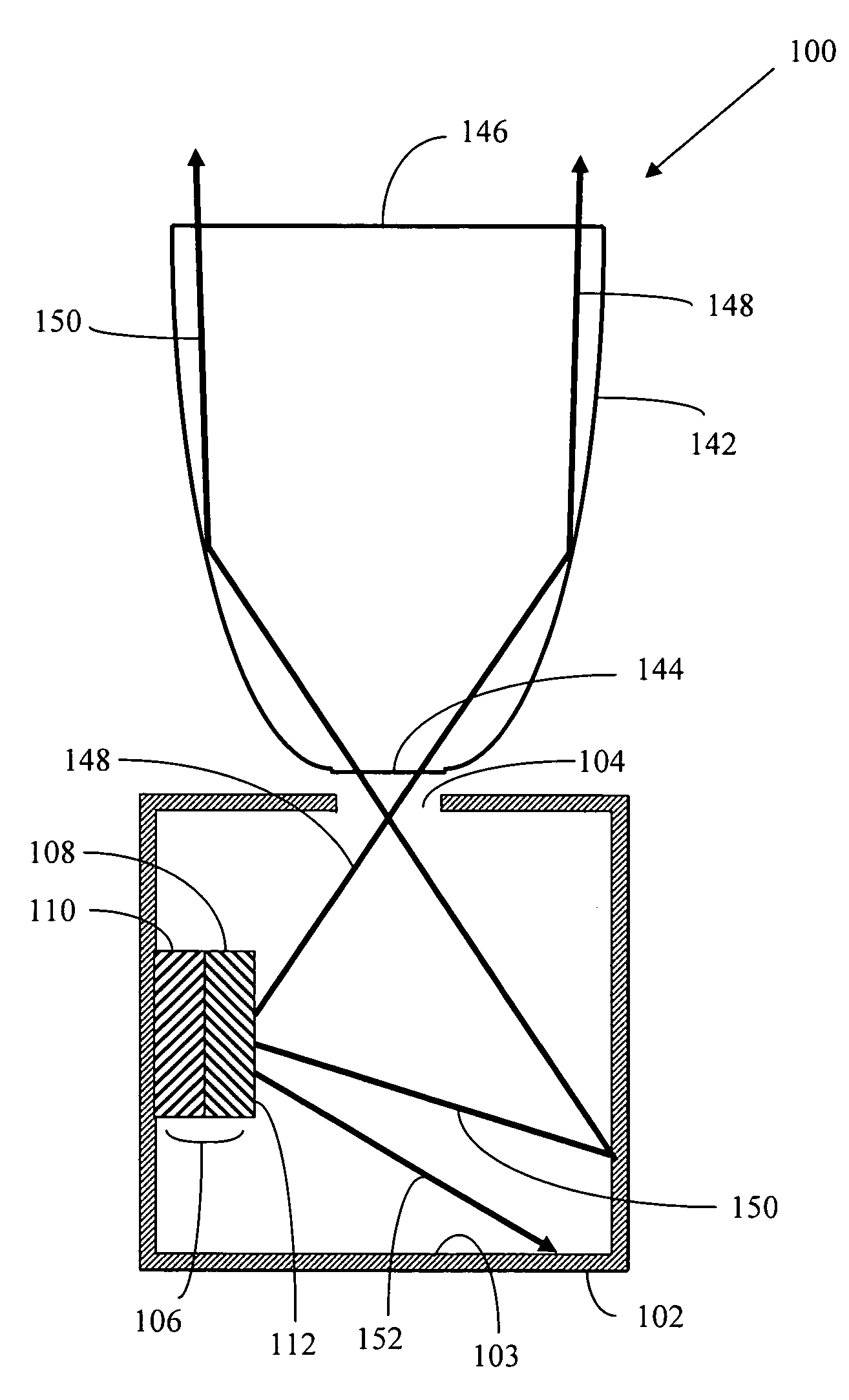
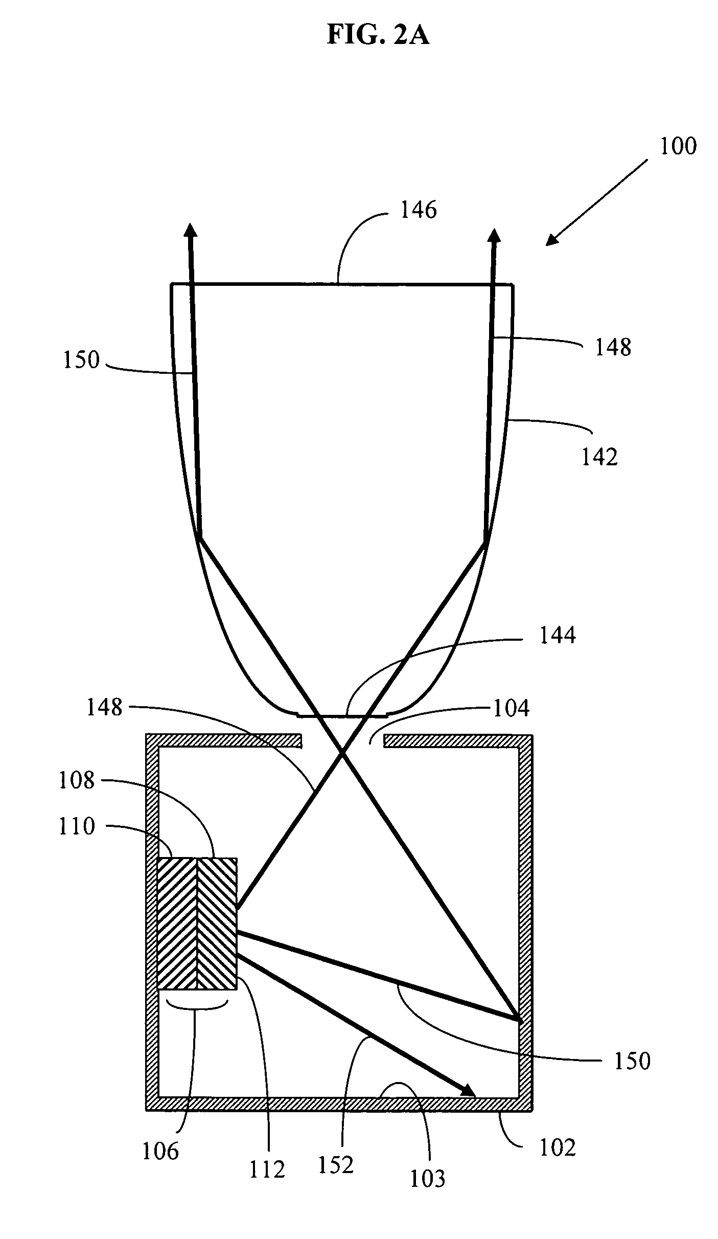
"This patent describes a projection display system that uses a light-recycling illumination system, a color scrolling means, and an imaging light modulator. The system generates light using a light-emitting diode and a reflecting layer, and a portion of the light is recycled back to the diode using a light-recycling envelope. The light is then output through a small aperture in the envelope, resulting in uncollimated light. The uncollimated light is partially collimated and directed to the color scrolling means, which sequentially scans bands of red, green, and blue light across an imaging light modulator. The modulator forms an image that is then projected onto a viewing screen. The technical effect of this system is that it allows for efficient use of light and improved image quality."

Problems solved by technology

Light sources such as LEDs are currently not used for projection display systems because LED sources do not have sufficient output brightness.
In a conventional imaging optical system that transports light in one direction from an input source at one location to an output image at a second location, one cannot produce an optical output image whose luminance is higher than the luminance of the light source.
This measurement is frequently misleading, since the sampling angle need not be defined.
The method and apparatus taught by U.S. Pat. No. 6,144,536 does not produce the combination of high brightness (luminance) and high flux (total lumens) within an output area sufficiently small enough for projection displays or other concentrated high intensity light source applications.
The linear light sources are not effective in coupling into small output areas due to the extended nature of the sources.
Unfortunately, even the very high brightness LEDs that have recently been developed lack both the total lumens and the luminance necessary to be used in projection and many high intensity light source applications.
While this performance is much improved over previous LEDs, they are still well below the levels created by the light sources used in projection and high intensity illumination systems.
However, the method taught will not provide a brightness enhancement independent of direction (mean spherical intensity).
However, narrowing the solid angle does not increase the total flux (lumens).
In addition, the light extraction means and the light transmitting means required by U.S. Pat. No. 6,144,536 are additional cumbersome elements that add extra expense and complication to fabricating a small area emitting light source.
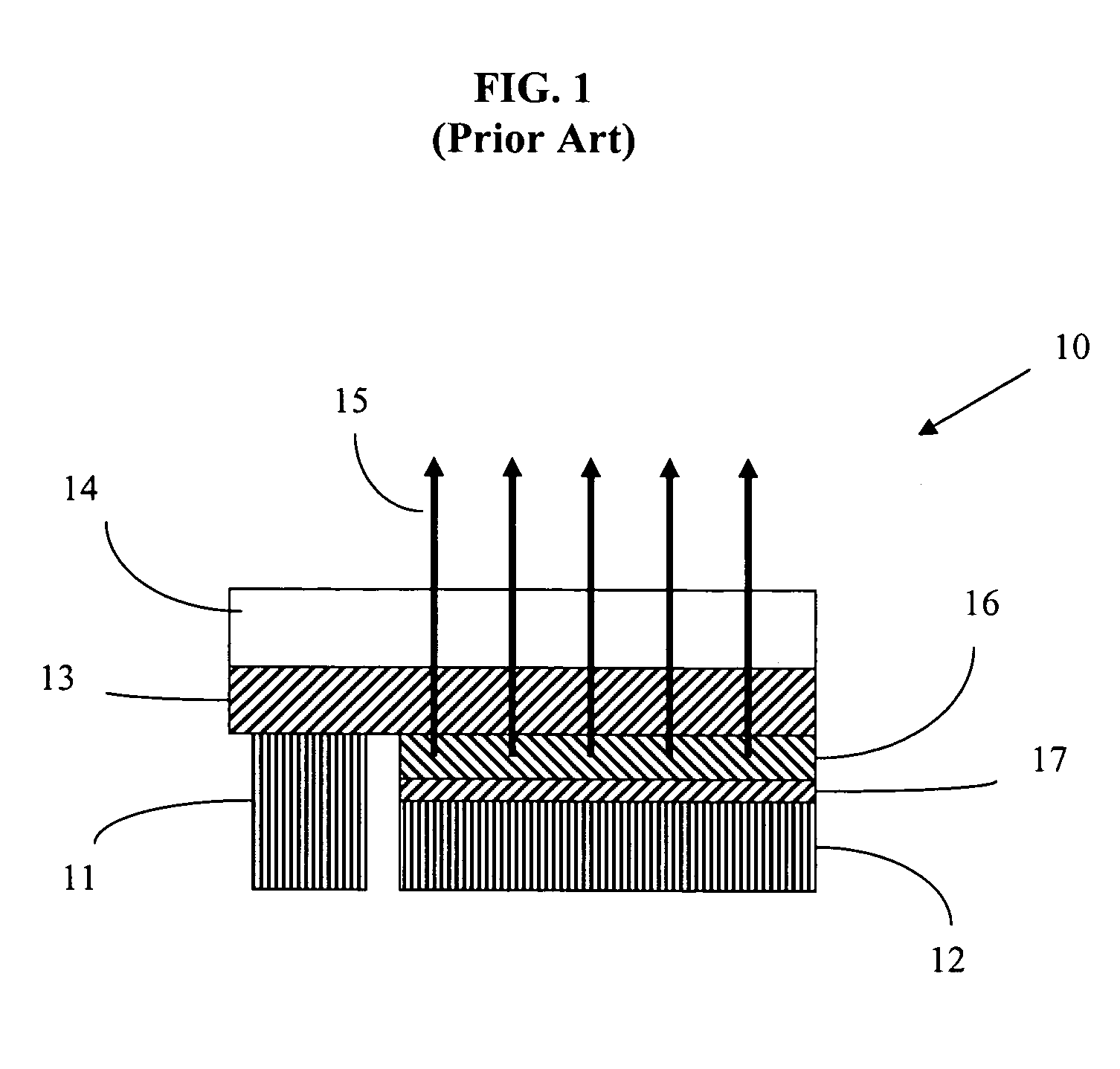
Typical prior LED designs placed one electrode on top of the device, which interfered with the light output from the top surface and resulted in devices with low reflectivity.
However, even the new green, cyan, blue and ultraviolet gallium nitride, indium gallium nitride, aluminum gallium nitride and aluminum nitride LEDs do not have sufficient luminance for many applications.
First, arc lamp sources have useful lifetimes that are typically shorter than the lifetime of the projection display system.
Lamp replacement, a costly and inconvenient process, is sometimes required.
Second, arc lamp sources may contain environmentally toxic materials such as mercury.
Third, color scrolling projection display systems that utilize arc lamps cannot be conveniently adjusted to change the color temperature or color balance of the light source.
The color temperature of an arc lamp source is determined by the properties of the arc and cannot be easily adjusted.

Method used


Image

  • Projection display systems utilizing color scrolling and light emitting diodes
  • Projection display systems utilizing color scrolling and light emitting diodes
  • Projection display systems utilizing color scrolling and light emitting diodes

Examples


Embodiment Construction

[0031]The preferred embodiments of the present invention will be better understood by those skilled in the art by reference to the above figures. The preferred embodiments of this invention illustrated in the figures are not intended to be exhaustive or to limit the invention to the precise form disclosed. The figures are chosen to describe or to best explain the principles of the invention and its applicable and practical use to thereby enable others skilled in the art to best utilize the invention.

[0032]The embodiments of this invention are comprised of at least one illumination system, a color scrolling means and an imaging light modulator. The illumination system is further comprised of a light source, a light-recycling envelope, a light-output aperture located in the surface of the light-recycling envelope and a light-collimating means.

[0033]The preferred light source of this invention comprises at least one light-emitting diode (LED). Preferred LEDs are inorganic light-emittin...


PUM

PropertyMeasurementUnit
wavelength rangeaaaaaaaaaa
wavelengthsaaaaaaaaaa

Abstract

A projection display system has at least one light-recycling illumination system, a color scroller and an imaging light modulator. The light-recycling illumination system includes a light source that is enclosed within a light-recycling envelope. The light source is a light-emitting diode that emits light, and a fraction of that light will exit the light-recycling envelope through an aperture. The light-recycling envelope recycles a portion of the light emitted by the light source back to the light source in order to enhance the luminance of the light exiting the aperture. The fraction of the light that exits the aperture is partially collimated and is directed to a color scrolling means. The color scroller scans the partially collimated light across the face of the imaging light modulator. The imaging light modulator spatially modulates the scrolled beam of light to form an image.

Description

CROSS REFERENCES TO RELATED APPLICATIONS[0001]This application is related to U.S. patent application Ser. No. 10 / 445,136 entitled “ILLUMINATION SYSTEMS UTILIZING HIGHLY REFLECTIVE LIGHT EMITTING DIODES AND LIGHT RECYCLING TO ENHANCE BRIGHTNESS,” which is herein incorporated by reference. This application is also related to U.S. patent application Ser. No. 10 / 814,043 entitled “ILLUMINATION SYSTEMS UTILIZING LIGHT EMITTING DIODES AND LIGHT RECYCLING TO ENHANCE OUTPUT RADIANCE,” to U.S. patent application Ser. No. 10 / 814,044 entitled “ILLUMINATION SYSTEMS UTILIZING MULTIPLE WAVELENGTH LIGHT RECYCLING” and to U.S. patent application Ser. No. 10 / 815,005 entitled “PROJECTION DISPLAY SYSTEMS UTILIZING LIGHT EMITTING DIODES AND LIGHT RECYCLING,” all of which are herein incorporated by reference.TECHNICAL FIELD[0002]This invention relates to projection display systems incorporating color scrolling and light-emitting diodes (LEDs).BACKGROUND OF THE INVENTION[0003]Applications such as projecti...

Claims


Application Information

Patent Timeline
Patent Type & Authority Patents(United States)
IPC IPC(8): G03B21/00G02F1/1335G03B21/14G03B21/28H04N9/12G03B21/20H04N9/31
CPCH04N9/3117H04N9/315H04N9/3155G03B33/10G03B21/2033G03B33/08H04N9/3197
Inventor BEESON, KARL W.ZIMMERMAN, SCOTT M.
Owner GOLDENEYE
Learn More