In-line centrifugal fan

a centrifugal fan and inline technology, applied in the direction of marine propulsion, vessel construction, other chemical processes, etc., can solve the problems of requiring reinstallation of non-modular moveable parts, affecting the efficiency of the system, so as to achieve the effect of convenient installation and service, improved efficiency and less nois

Inactive Publication Date: 2006-05-23
GREENHECK FAN
View PDF15 Cites 64 Cited by
  • Summary
  • Abstract
  • Description
  • Claims
  • Application Information

AI Technical Summary

Benefits of technology

[0010]In accordance with another aspect of the invention, the inlet cone has a discharge diameter of approximately between 0.68 and 0.83 times the diameter defined by radial outermost edges of opposing fan blades. The geometric configuration of the inlet cone contributes to the fan's enhanced aerodynamic and acoustic performance, thereby resulting in reduced sound levels and increased efficiency during operation when compared to conventional inline centrifugal fans.
[0014]In accordance with another aspect of the invention, the fan includes a modular bearing assembly that extends within the conduit. The bearing assembly includes a shaft that is driven by the electric motor. The shaft, in turn, drives the impeller and first and second bearing plates mounted within the drive chamber. The bearing assembly is removable from the conduit as a unitary assembly, which allows the fan to be easily serviced when access to the fan's internal drive components has been quite limited and cumbersome in conventional inline centrifugal fans.
[0015]In accordance with another aspect of the invention, a duct connector is disposed proximal the intake end and is unitary with the conduit. The duct connector is configured to provide a slip-fit connection with ductwork in a building, thereby allowing the fan to be installed in a building, for example, with greater ease than inline centrifugal fans currently available.
[0024]Each of these aspects independently and / or in combination produce a fan that is more efficient and less noisy than conventional fans, and further allow the fan to be more easily installed and serviced when compared to conventional fans.
[0025]For example, the present invention produces a fan that is capable of producing sound levels less than 70 decibels when operating with an airflow of substantially 4100 cubic feet per minute and one inch water gauge of fan static pressure. The present invention further produces a fan that is capable of achieving an efficiency of greater than 40% when operating with an airflow at a rate between 4100 and 6100 cubic feet per minute at substantially one inch water gauge of fan static pressure. The present invention further produces a fan that is capable of producing sound levels less than 70 decibels when operating with an airflow at a rate between 4100 and 6100 cubic feet per minute at substantially one inch water gauge of fan static pressure. The present invention further produces a fan that is capable of achieving an efficiency greater than 60% when producing an airflow at a rate between 4100 and 6100 cubic feet per minute at 2 inches water gauge of static pressure. The present invention further produces a fan that is capable of achieving sound levels less than 78 dBA when producing an airflow at a rate between 4100 and 20000 cubic feet per minute at 3 inches of water gauge static pressure. Accordingly, the fan greatly reduces noise pollution with respect to inline centrifugal fans currently available. Furthermore, the increased efficiencies reduce the cost associated with operating the fan compared to inline centrifugal fans currently available.

Problems solved by technology

Furthermore, servicing conventional fans' internal drive components has typically been limited and cumbersome due to the limited accessibility to their internal drive components, which requires the removal, and disassembly, of other internal components.
Subsequently, the non-modular moveable parts need to be reinstalled within the fan, which is difficult given the small internal confines of the fan.

Method used


Image

  • In-line centrifugal fan
  • In-line centrifugal fan
  • In-line centrifugal fan

Examples


Embodiment Construction

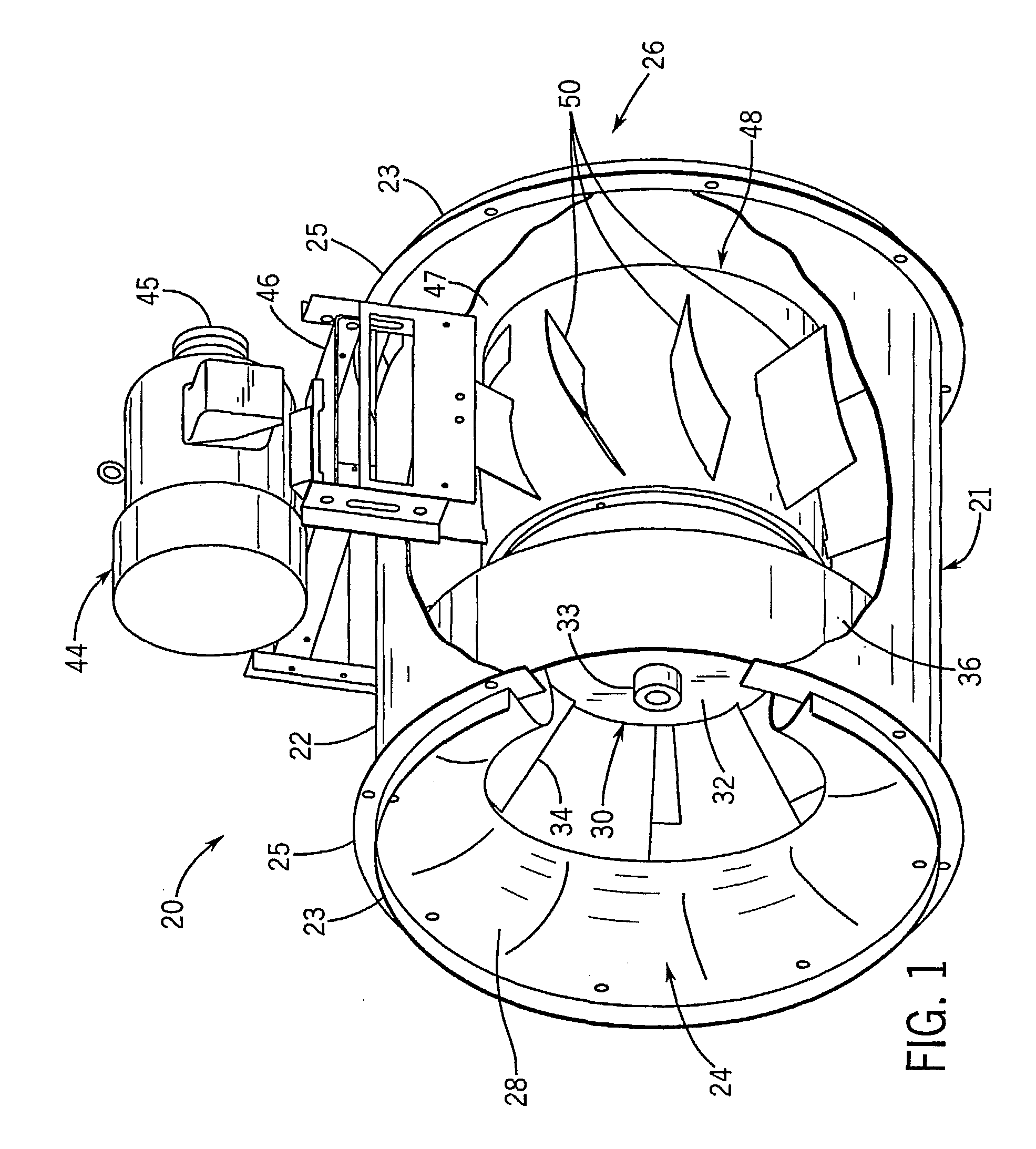
[0042]Referring initially to FIGS. 1 and 4, an in-line centrifugal fan 20, preferably a mixed flow fan, includes a housing 21 defining an annular conduit 22. The conduit 22 includes an air intake end 24 that receives air to be circulated, and an air outlet end 26 downstream of the intake end that expels the air from the fan at a predetermined flow rate. While the fan 20 is a mixed flow fan, it should be appreciated throughout this description that the terms “upstream” and “downstream” are used herein with respect to the flow of air through fan 20 in the axial direction from the intake end 24 towards the outlet end 26. An electric motor 44 is mounted onto the upper surface of housing 21 via a mounting bracket 46 and, during operation, rotates a drive pulley 45 at a predetermined rate. A drive belt (not shown) translates the power from the drive pulley 45 to rotate the corresponding internal components of fan 20, thus circulating air throughout, for example, a building. It should be a...


PUM


Abstract

An inline centrifugal mixed flow fan (20) includes an axially extending intake conduit (22). An inlet cone (28) is disposed at an intake end (24). An impeller (30) is disposed downstream of the inlet cone and includes a centrally disposed wheel-back (32) rotated by an electric motor (44), plural fan blades (34) extending radially outwardly from the wheel-back and a wheel cone fixedly (36) attached to and circumscribing the wheel blades. A driver chamber (48) downstream of the impeller includes plural radially extending straight vanes (50) to direct air to an outlet end (26). The fan is configured to achieve reduced sound level and increased efficiency.

Description

CROSS-REFERENCE TO RELATED APPLICATIONS[0001]This application claims the benefit provisional U.S. application 60 / 211,741, entitled “In-Line Centrifugal Fan” which was filed on Jun. 15, 2000, the disclosure of which is hereby incorporated by reference as if set forth in its entirety herein.STATEMENT REGARDING FEDERALLY SPONSORED RESEARCH OR DEVELOPMENT[0002]Not applicable.BACKGROUND OF THE INVENTION[0003]The present invention relates generally to an in-line centrifugal fan, and in particular, relates to a mixed flow fan having a high operating efficiency and reduced sound output, and that is easy to manufacture and service.[0004]In-line fans are generally classified according to the direction of airflow through the impeller. In particular, axial flow fans are characterized by flow through the impeller in a direction generally parallel to the shaft axis. In-line centrifugal fans receive airflow into the impeller axially, and redirect the airflow radially outward. Mixed flow fans are c...

Claims


Application Information

Patent Timeline
Patent Type & Authority Patents(United States)
IPC IPC(8): F04D29/38F04D17/06F04D17/16F04D29/30
CPCF04D17/06F04D29/30F04D17/165Y10S416/02
Inventor MATHSON, TIMOTHY R.KUSKI, TIMOTHY D.
Owner GREENHECK FAN
Why Eureka
Try Eureka