
Rare-earth sintered magnet and method of producing the same

a rare earth magnet and rare earth technology, applied in the field can solve the problems of insufficient heat resistance of rare earth magnets, inability to realize inability to achieve the effect of realizing the effect of magnetization,

Inactive Publication Date: 2006-05-23
HITACHI METALS LTD
View PDF11 Cites 29 Cited by
  • Summary
  • Abstract
  • Description
  • Claims
  • Application Information

AI Technical Summary

Benefits of technology

The present invention provides rare-earth sintered magnets with improved magnetic properties by reducing the amount of non-magnetic phase in the grain boundary and increasing the concentration of rare-earth elements in the grain boundary phase. The magnets have a composition of (R1x+R2y)T100-x-y-z-rQzM, wherein molar fractions x, y, z, p, q, and r satisfy specific requirements. The invention also provides a method for producing the rare-earth sintered magnets and a rare-earth alloy powder for use in the magnets. The technical effects of the invention include improved magnetic properties, reduced non-magnetic phase in the grain boundary, and increased concentration of rare-earth elements in the grain boundary phase.

Problems solved by technology

However, Nd and / or Pr existing in a grain boundary phase form a non-magnetic phase and do not contribute to the improvement of magnetization.
However, techniques for realizing this did not exist in the prior art.
However, the heat resistance of an R—Fe—B rare-earth magnet is not sufficient for use under a high temperature environment such as those experienced by a motor in an automobile.
Thus, a part of Co added is not used for substituting Fe but is wasted in the grain boundary phase.
Another problem is that the above compounds are a ferromagnetic substance and thus decreases the coercive force of the sintered magnet.
Therefore, simply increasing the amount of Co to be added is not an effective way to substitute Fe in the main phase, and doing do can substantially decrease the coercive force of an R—Fe—B rare-earth magnet.

Method used


Image

  • Rare-earth sintered magnet and method of producing the same
  • Rare-earth sintered magnet and method of producing the same
  • Rare-earth sintered magnet and method of producing the same

Examples


embodiment 2

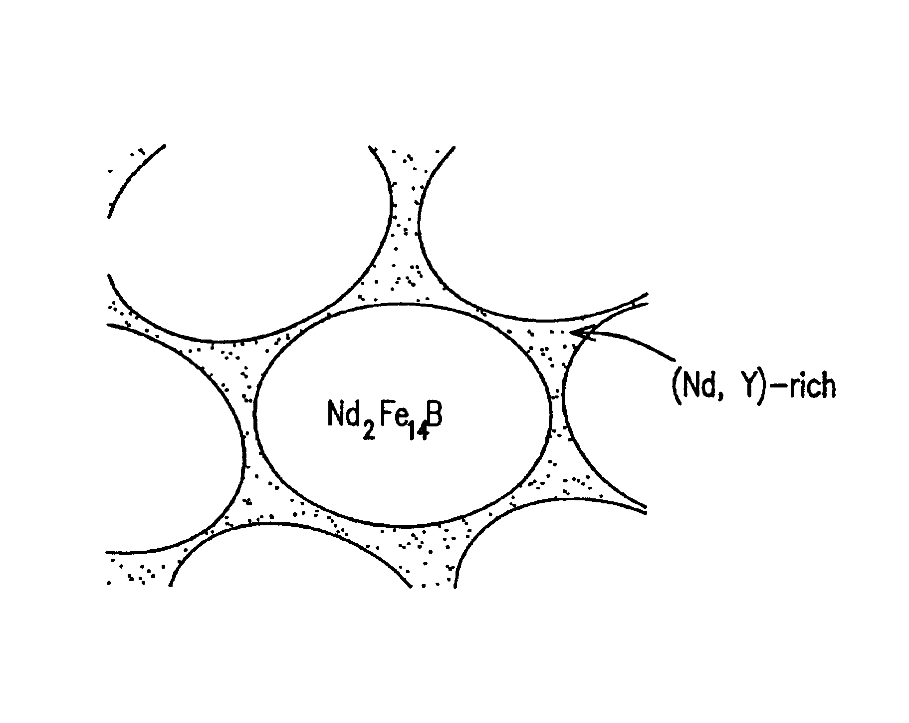
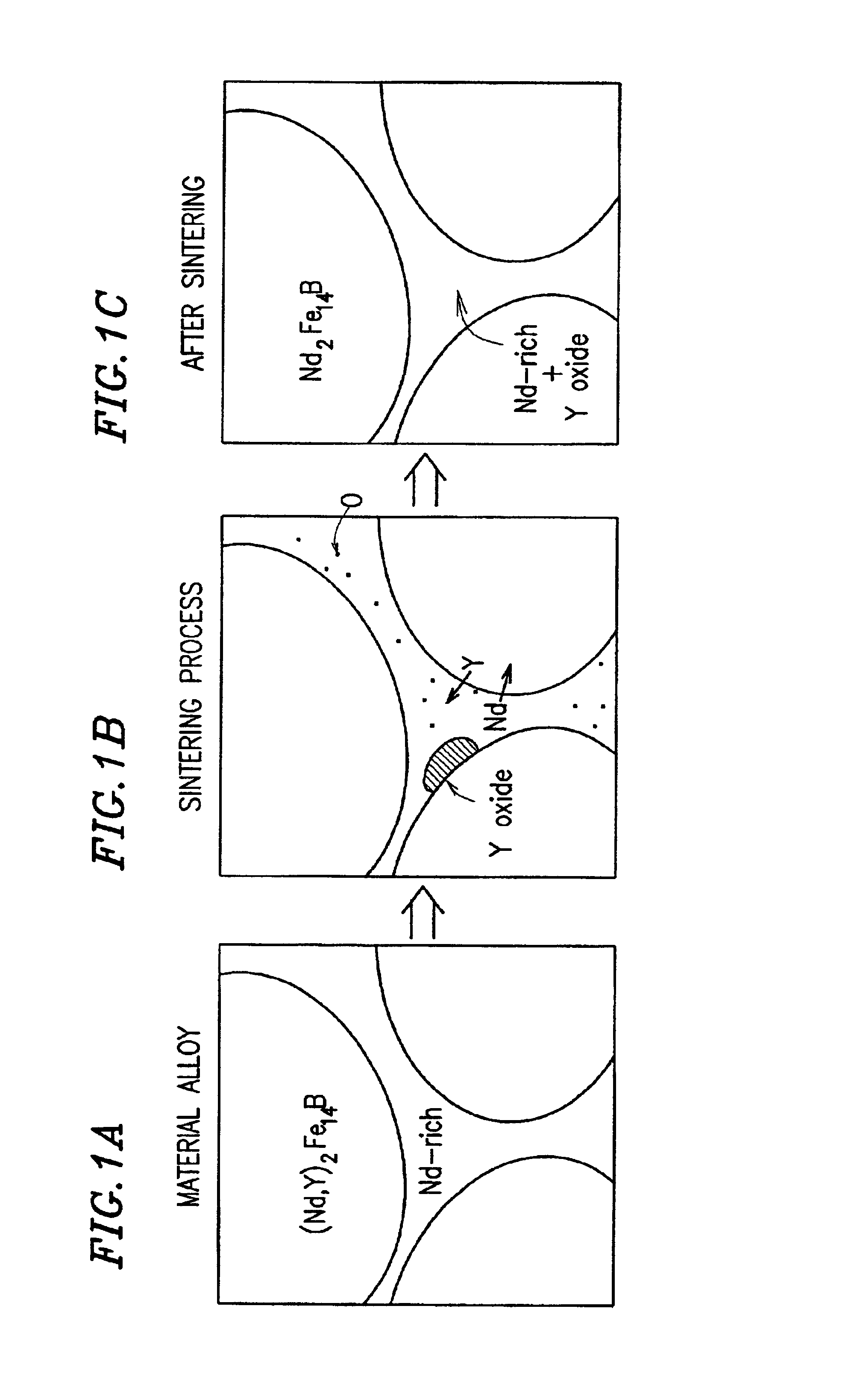
[0100]A second embodiment of the present invention will now be described. In the present embodiment, Y, La and / or Sc are added, in addition to Nd and / or Pr, and these elements are concentrated in a grain boundary phase, so that an amount of a transition metal such as Co that would otherwise be consumed for the formation of a ferromagnetic compound in the grain boundary phase is taken into the main phase crystal grains. In this way, Fe in the main phase (Nd2Fe14B phase) providing hard magnetism is efficiently substituted with Co, etc.

[0101]If Co is added in the present invention, a large amount of Co is present in the Nd2Fe14B phase, which is the main phase. In contrast, if, as in the prior art, Co is added in large amounts without adding Y, La or Sc, a large amount of Co is present also in the grain boundary phase, thereby forming a ferromagnetic compound in the grain boundary phase. As described above, when a large amount of a ferromagnetic compound such as NdCo2 is formed in the g...

example

[0144]An example of the second embodiment of the present invention will now be described.

[0145]In this example, various material alloy compositions represented by (R1x+R2y)(T1p+T2q) 100-x-y-z-rQzMr were prepared, where R1 is Nd and Dy, R2 is Y (Yttrium), T1 is Fe, T2 is Co, Q is B (boron), and M is Cu and Al. Each composition was adjusted so as to contain 5 to 10 at % of Nd, 4 at % of Dy, 0 to 5 at % of Y, 0 to 6 at % of Co, 6 at % of B, 0.2 at % of Cu, and 0.4 at % of Al, with the balance being the amount of Fe.

[0146]Each alloy composition was heated to about 1400° C. in an Ar atmosphere to obtain a molten alloy, and the molten alloy was poured into a water-cooled mold. The molten alloy was cooled to obtain a solidified alloy having a thickness of about 5 mm.

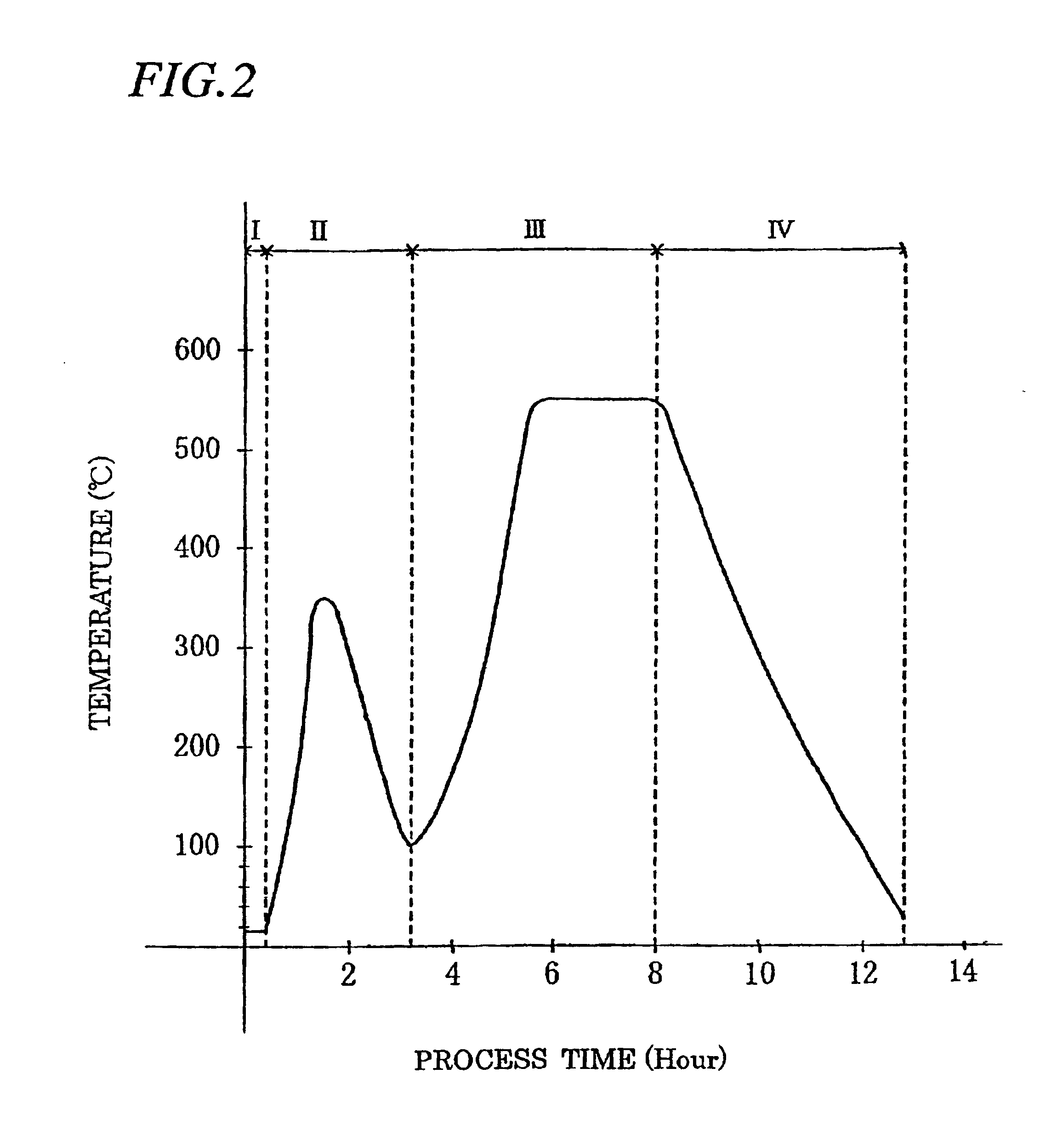
[0147]After the solidified alloy was allowed to occlude hydrogen, it was heated to about 600° C. while evacuating the atmosphere so as to be embrittled (hydrogen pulverization process). A coarsely pulverized powder was obtained...


PUM

PropertyMeasurementUnit
temperatureaaaaaaaaaa
particle sizeaaaaaaaaaa
sizeaaaaaaaaaa

Abstract

The present invention provides a rare-earth sintered magnet exhibiting desirable magnetic properties in which the amount of Nd and / or Pr forming a non-magnetic phase in a grain boundary phase is reduced. Specifically, the present invention provides a rare-earth sintered magnet having a composition of (R1x+R2y)T100-x-y-zQz where R1 is at least one element selected from the group consisting of all rare-earth elements excluding La (lanthanum), Y (yttrium) and Sc (scandium); R2 is at least one element selected from the group consisting of La, Y and Sc; T is at least one element selected from the group consisting of all transition elements; Q is at least one element selected from the group consisting of B and C, and including, as a main phase, a crystal grain of an Nd2Fe14B crystalline structure, wherein: molar fractions x, y and z satisfy 8≦x≦18 at %, 0.1≦y≦3.5 at % and 3≦z≦20 at %, respectively; and a concentration of R2 is higher in at least a part of a grain boundary phase than in the main phase crystal grains.

Description

BACKGROUND OF THE INVENTION[0001]1. Field of the Invention[0002]The present invention relates to an R—Fe—B rare-earth magnet and a method of producing the same.[0003]2. Description of Related Art[0004]In the prior art, neodymium (Nd) and / or praseodymium (Pr) have primarily been used as the rare-earth element R of an R—Fe—B rare-earth magnet because the use of these rare-earth elements provides particularly desirable magnetic properties.[0005]In recent years, the variety of applications of R—Fe—B magnets has expanded, and the Nd and Pr consumption is increasing rapidly. Accordingly, there is a strong demand to improve the efficiency of use of Nd and Pr, which are precious natural resources, and for reducing the material cost of an R—Fe—B magnet.[0006]The simplest way to reduce the Nd and Pr consumption is to substitute Nd and Pr with another rare-earth element that functions similarly to Nd and Pr. It is known in the art, however, that the magnetic properties, such as magnetization, ...

Claims


Application Information

Patent Timeline
Patent Type & Authority Patents(United States)
IPC IPC(8): H01F1/057H01F1/058
CPCH01F1/058H01F1/0577H01F1/057
Inventor KANEKO, YUJITANIGUCHI, KATSUYASEKINO, TAKAO
Owner HITACHI METALS LTD
Learn More