Laminated ceramic capacitor

a laminated ceramic capacitor and capacitor technology, applied in the direction of fixed capacitors, stacked capacitors, fixed capacitor details, etc., can solve the problems of frequent defective connection to the terminal electrode, poor yield rate of laminated ceramic capacitors, etc., and achieve the effect of reducing defective connections

Active Publication Date: 2006-05-23
TDK CORPARATION
View PDF10 Cites 64 Cited by
  • Summary
  • Abstract
  • Description
  • Claims
  • Application Information

AI Technical Summary

Benefits of technology

[0007]An object of the present invention is to provide a laminated ceramic capacitor being capable of reducing defective connections between internal electrodes and terminal electrodes.
[0008]Another object of the present invention is to provide a laminated ceramic capacitor being capable of reducing occurrence of delamination.
[0009]Yet another object of the present invention is to provide a laminated ceramic capacitor being capable of reducing occurrence of cracks.

Problems solved by technology

Therefore, a laminated ceramic capacitor having a plurality of terminal pairs has had a problem that defective connections occur frequently between internal and terminal electrodes and the yield rate of it is worsened due to a smaller number of internal electrodes exposed at a side of a ceramic body in comparison with a conventional laminated ceramic capacitor.
Further, with the miniaturization of a laminated ceramic capacitor, since a part to be exposed at a side of a ceramic body and connected to a terminal electrode is made smaller, a conventional laminated ceramic capacitor also has had a problem that defective connection to a terminal electrode occurs frequently.

Method used


Image

  • Laminated ceramic capacitor
  • Laminated ceramic capacitor
  • Laminated ceramic capacitor

Examples


Embodiment Construction

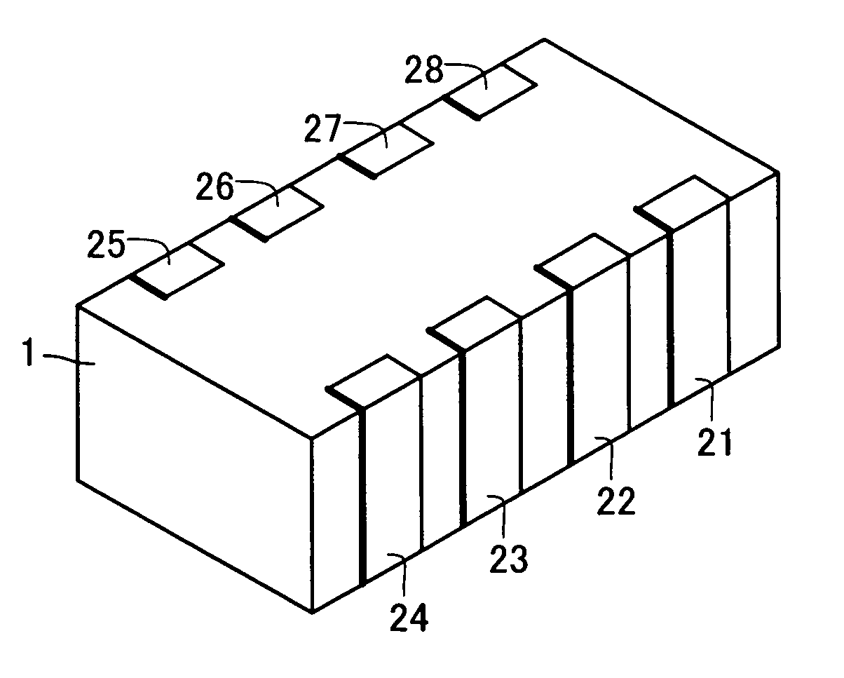
[0039]A laminated ceramic capacitor illustrated is a laminated ceramic capacitor having a plurality of terminal pairs and is used in CPU decoupling and the like, for example.

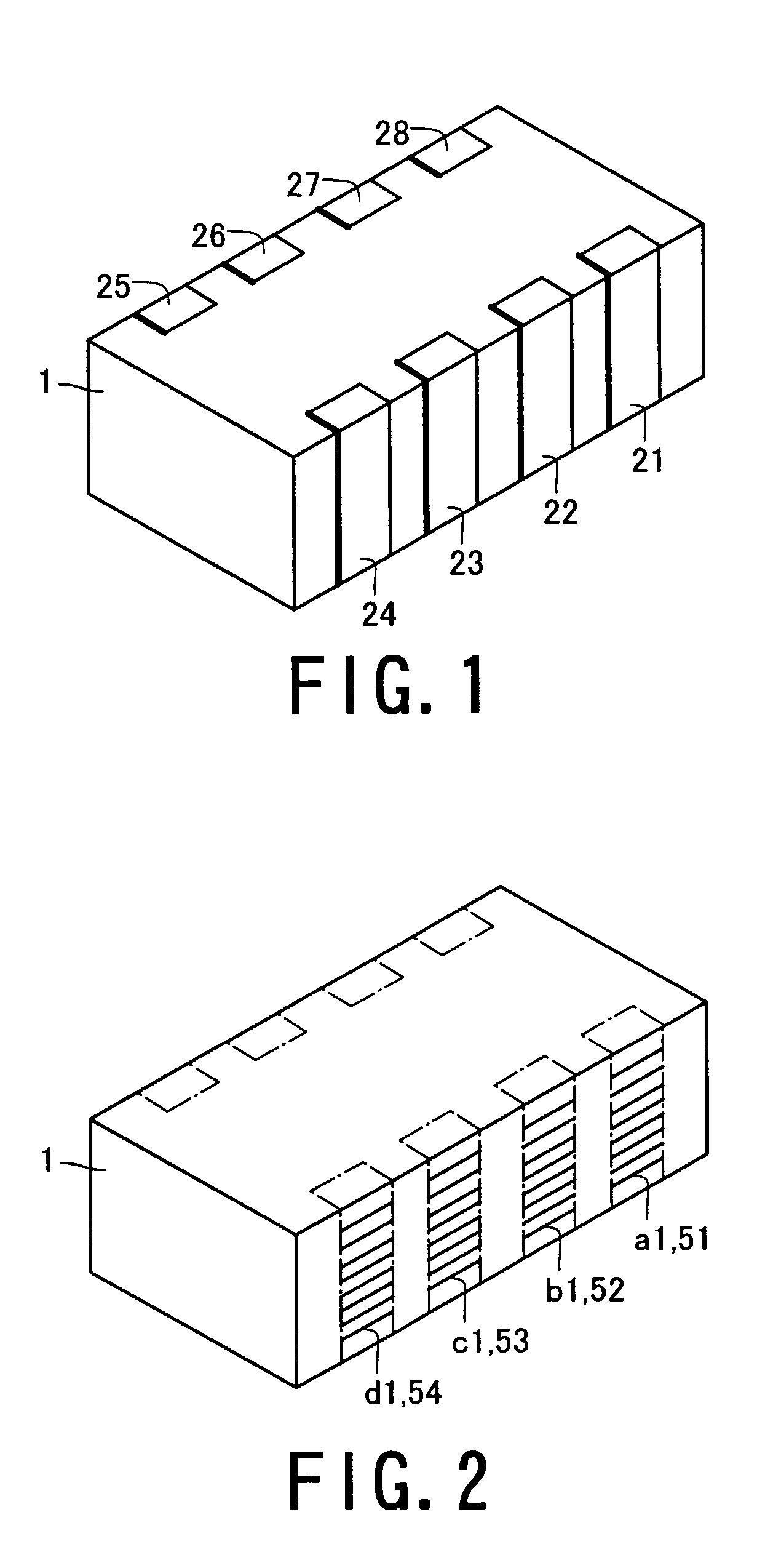
[0040]As shown in FIGS. 1 to 5, a laminated ceramic capacitor comprises a ceramic body 1, internal electrodes A1 to D1 and A2 to D2, dummy electrodes 51 to 58, and terminal electrodes 21 to 28. The ceramic body 1 includes a ceramic dielectric.

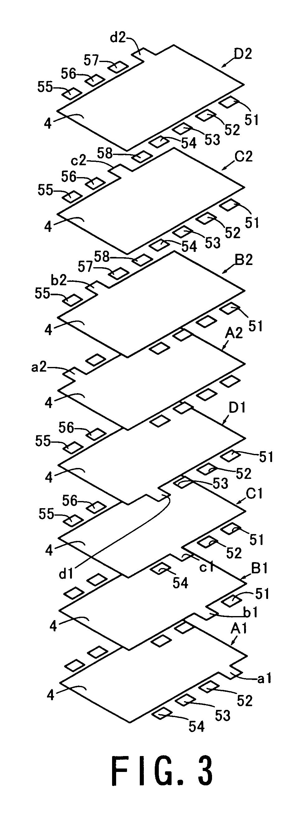
[0041]In FIG. 3, the internal electrodes A1 to D1 and A2 to D2 each comprise one of lead electrodes a1 to d1 and a2 to d2 and a facing electrode 4, and are laid in layers at spaces in the direction of thickness of the ceramic body 1. The internal electrodes A1 and A2, B1 and B2, C1 and C2, and D1 and D2 respectively have the same shape as each other in pairs, and are turned from each other by 180 degrees in lamination.

[0042]In FIG. 3, the internal electrodes A1 to D1 and A2 to D2 are laminated one over another with ceramic body 1 between them in order of A1, B1, C1, D1, A2,...


PUM

PropertyMeasurementUnit
thicknessaaaaaaaaaa
capacitanceaaaaaaaaaa
widthaaaaaaaaaa

Abstract

Internal electrodes A1 to D1 and A2 to D2 are laid in layers at spaces in the direction of thickness of a ceramic body 1. Lead electrodes a1 to d1 and a2 to d2 are led out to a side face to form lead portions. Dummy electrodes 51 to 58 have one-side ends led out to a side face to form lead portions in layers provided with the internal electrodes A1 to D1 and A2 to D2. The lead portion of a lead electrode a1 to d1 or a2 to d2 of each layer is superposed over the lead portion of a dummy electrode 51 to 58 belonging to another layer in the direction of thickness.

Description

TECHNICAL FIELD[0001]The present invention relates to a laminated ceramic capacitor.BACKGROUND OF THE INVENTION[0002]As a laminated ceramic capacitor, there is known a laminated ceramic capacitor having a plurality of terminal pairs, for example. A ceramic capacitor having a plurality of terminal pairs is used for decoupling a central processing unit (CPU) of a personal computer, and the like. For example, Patent Literature 1 (Japanese published patent application No. 2002-184647) has disclosed an internal electrode pattern of a laminated ceramic capacitor having eight terminals and a method for manufacturing the same.[0003]And Patent Literature 2 (Japanese published patent application No. 2003-31435) has disclosed a laminated ceramic capacitor having eight terminals, being provided with a filling layer (dummy electrode) in a part having no lead electrode provided in it in order to prevent a ceramic dielectric layer from being depressed.[0004]While a conventional laminated ceramic c...

Claims


Application Information

Patent Timeline
Patent Type & Authority Patents(United States)
IPC IPC(8): H01G4/005H01G4/12H01G4/228H01G4/30H01G4/38
CPCH01G4/005H01G4/30
Inventor AHIKO, TAISUKEMASUDA, SUNAOTOGASHI, MASAAKI
Owner TDK CORPARATION
Why Eureka
Try Eureka