Variable volume valve for a combustion powered tool

a technology of constant volume valve and combustion engine, which is applied in the direction of manufacturing tools, machines/engines, nailing tools, etc., can solve the problems of flow rate also changing, and achieve the effect of constant energy to the tool

Inactive Publication Date: 2006-05-30
ILLINOIS TOOL WORKS INC
View PDF41 Cites 4 Cited by
  • Summary
  • Abstract
  • Description
  • Claims
  • Application Information

AI Technical Summary

Benefits of technology

[0014]These and other objects are met or exceeded by the present device for metering a constant volume of fluid to provide constant energy to a tool. This apparatus is most useful in a portable fastening tool powered either pneumatically or by an internal ...

Problems solved by technology

However, in a flow system, flow rates will also chang...

Method used


Image

  • Variable volume valve for a combustion powered tool
  • Variable volume valve for a combustion powered tool
  • Variable volume valve for a combustion powered tool

Examples


Embodiment Construction

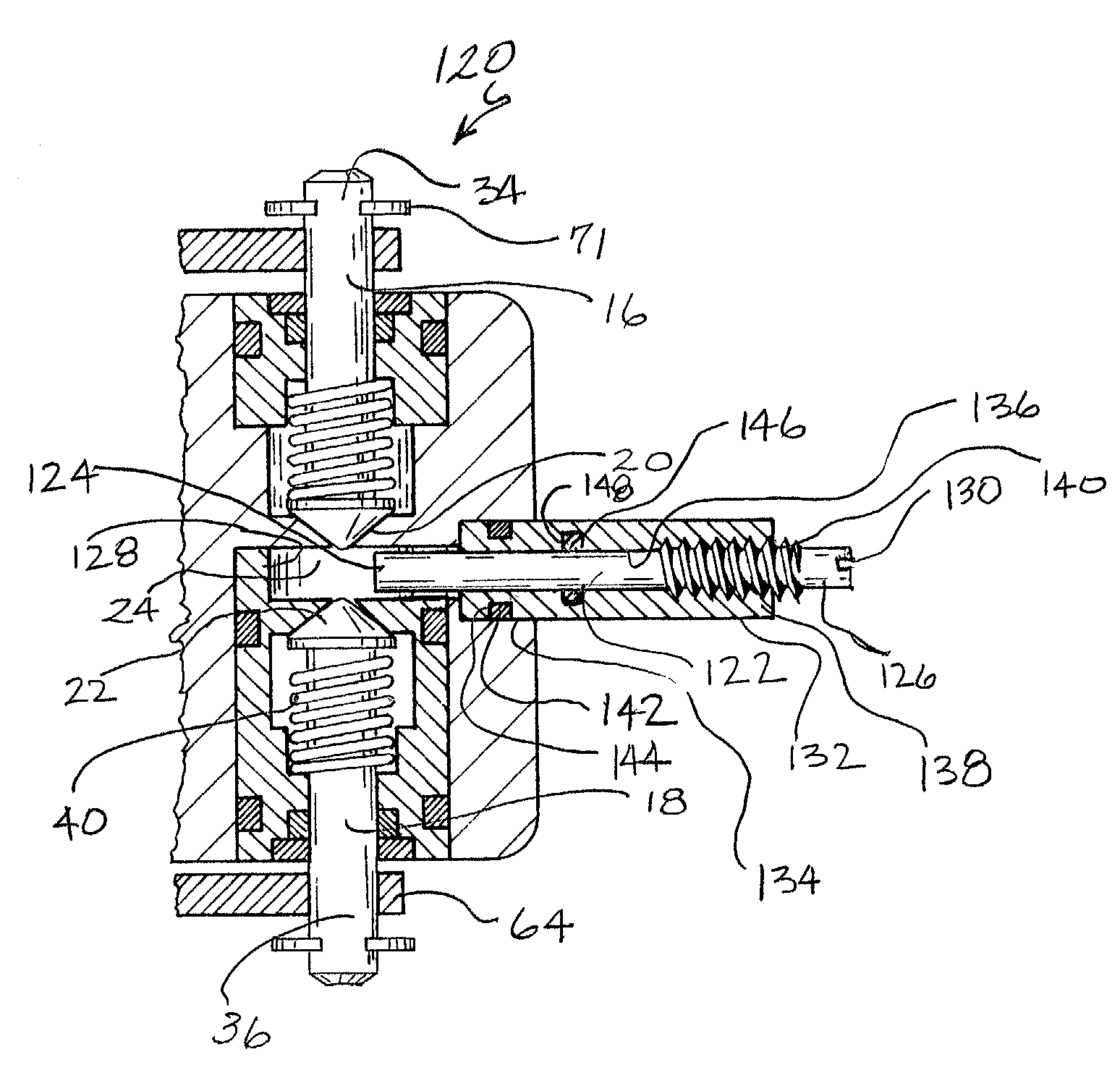
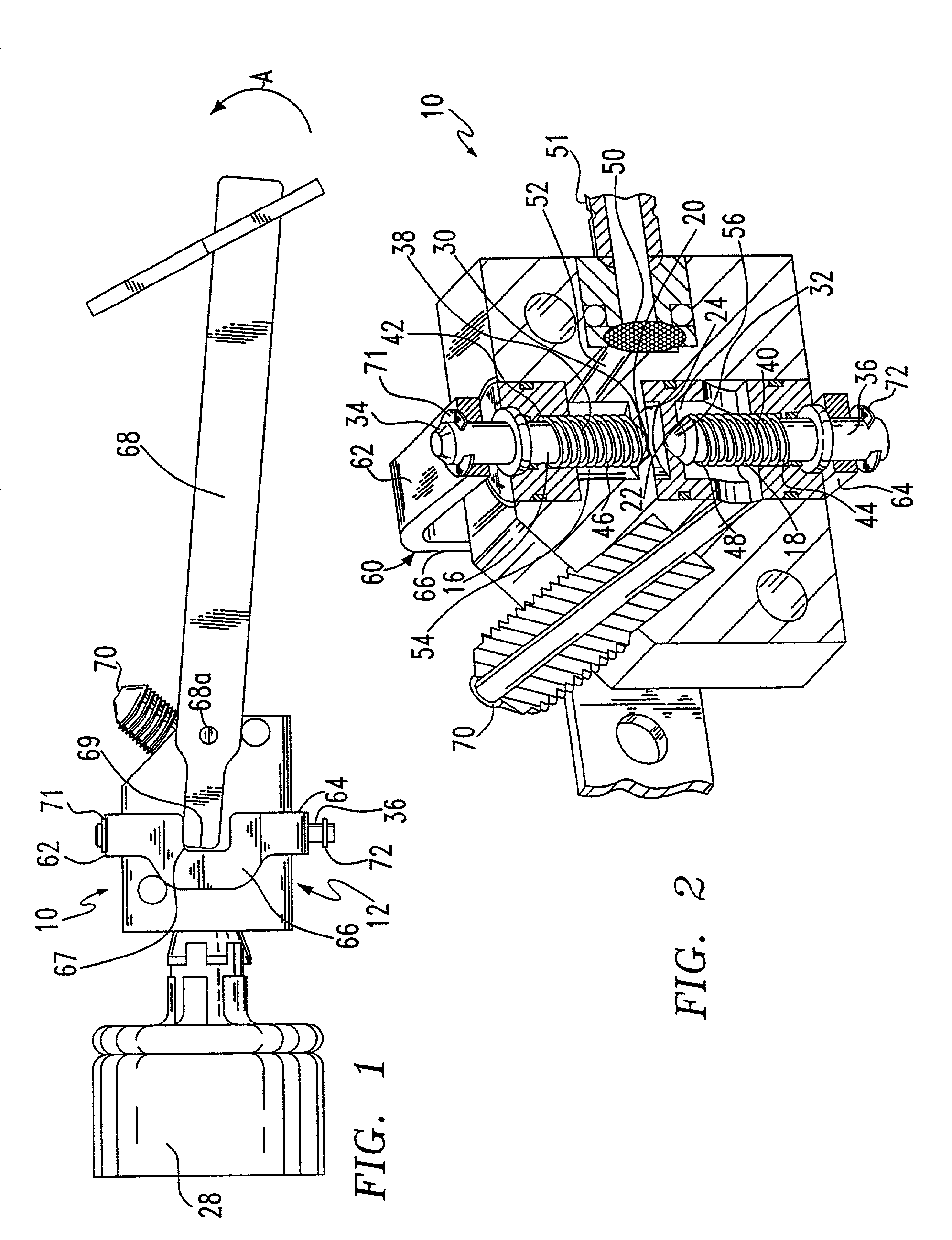
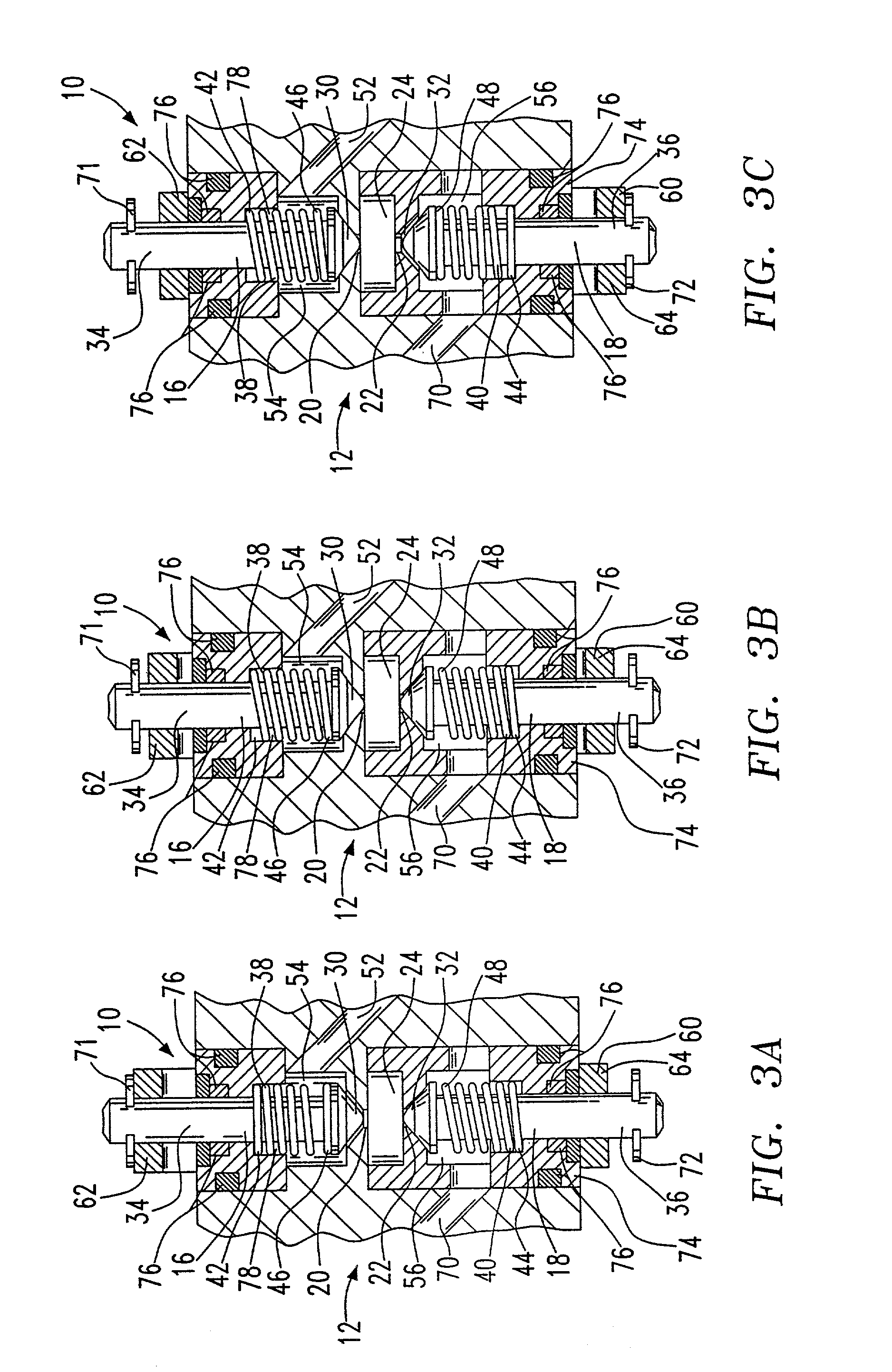
[0030]Referring to FIGS. 1 and 2, a constant volume valve assembly and metering chamber is, generally designated 10. In the following description, the terms “upper” and “lower” refer to the assembly in the orientation shown in the drawings. However, it is contemplated that the present assembly may be used in a variety of positions as is well known in the art. The present valve assembly 10 is particularly useful in a pneumatic or combustion powered tool (not shown), having a valve housing 12 in which the fluid to be metered is injected under pressure. The valve assembly 10 provides a fixed amount of fuel to the combustion chamber (not shown) of the tool. Alternatively, it is contemplated that the present valve assembly 10 may also meter pressurized air, which expands to provide power, to the pneumatic tool. The present valve assembly 10 is usable in any tool or device that would benefit from a steady, uniform supply of a pressurized fluid.

[0031]The housing 12 of the valve assembly 10...


PUM


Abstract

A variable volume metering chamber and valve assembly for a combustion-powered tool includes a housing defining a metering chamber having an internal volume and including an inlet and an outlet, and a plunger configured for reciprocal movement relative to the chamber for adjusting the internal volume of the metering chamber. The plunger is preferably adjustable by the user to alter the volume of fuel retained in the metering chamber. In the housing, a first valve controls control fluid flow through the inlet, a second valve controls fluid flow through the outlet, and an actuator assembly, connected to the valves, is sequentially operable from a first position, in which the first valve is open and the second valve is closed, to a second position, in which the first and second valves are both closed, and a third position, in which the first valve is closed and the second valve is open.

Description

RELATED APPLICATION[0001]This application is a continuation-in-part of U.S. Ser. No. 09 / 849,706 filed May 4, 2001 for CONSTANT VOLUME VALVE FOR A COMBUSTION POWERED TOOL now U.S. Pat. No. 6,655,570.BACKGROUND OF THE INVENTION[0002]The present invention relates to a constant volume valve for a combustion-powered tool, such as a power framing tool. More specifically, it relates to a constant volume valve assembly that measures a volume of a fluid before allowing it to flow into a combustion chamber.[0003]This invention also relates to a pneumatically powered, combustion-powered, or other rapidly acting, fastener-driving tool of a type utilizing collated fasteners. Typically, as exemplified in Nikolich U.S. Pat. Re. 32,452, Nikolich U.S. Pat. No. 4,522,162; Nikolich U.S. Pat. No. 4,483,474; Nikolich U.S. Pat. No. 4,403,722 and Wagdy U.S. Pat. No. 4,483,473, which are herein incorporated by reference, a combustion-powered, fastener-driving tool comprises a combustion chamber, which is d...

Claims


Application Information

Patent Timeline
IPC IPC(8): F02B71/00B25C1/08
CPCB25C1/08
Inventor SHKOLNIKOV, YURYDEIESO, TONYTAYLOR, WALTER J.
Owner ILLINOIS TOOL WORKS INC
Why Eureka
Try Eureka