Gas delivery system with integrated valve manifold functionality for sub-atmospheric and super-atmospheric pressure applications

a gas delivery system and integrated valve technology, applied in the direction of liquid cleaning, container discharging methods, separation processes, etc., can solve the problems of affecting the gas supply system and the gas supply system, the failure of the other process, and the vulnerability of the two semiconductor manufacturing processes utilizing the single gas supply/dual outlet arrangement to problems and failures in the other process, so as to achieve the effect of ensuring the gas supply system is fully functional

Inactive Publication Date: 2006-05-30
ADVANCED TECH MATERIALS INC
View PDF3 Cites 20 Cited by
  • Summary
  • Abstract
  • Description
  • Claims
  • Application Information

AI Technical Summary

Benefits of technology

[0020]In another aspect, the invention relates to a method of supplying gas to multiple gas-utilizing process units from a gas cabinet including an enclosure containing a gas supply vessel, such method including, in a first mode of operation, flowing gas from the gas supply vessel through a flow circuitry including multiple sticks each of which is arranged for gas flow communication to a respective gas-utilizing process unit, and in a second mode of operation, isolating portions of the flow circuitry associated with selected ones of the multiple sticks from other portions of the flow circuitry, so that gas can be flowed to one or more of the sticks, while evacuating and purging other sticks, or otherwise closing same to flow of gas therethrough.

Problems solved by technology

One problem associated with such use of a manual valve is the absence of any automatic interlocking capability for independent isolation of each of the outlets.
As a result, each of the two semiconductor manufacturing processes utilizing the single gas supply / dual outlet arrangement are vulnerable to problems and failures in the other process.
For example, if one process tool experiences backflow of the delivered gas, both processes being supplied with gas from the gas cabinet will be affected.
Further, if one process tool has an alarm that actuates shut-off of the gas supply, both processes will be terminated by the resulting stoppage of gas flow.
Additionally, routine maintenance, such as purging and evacuation of process lines, cannot be carried out utilizing the vacuum generator and purge gas supply that is conventionally associated with the cabinet, if gas flow is maintained on one of the two outlets.
The problem with the foregoing VMB arrangement is that the VMB unit is relatively expensive, so that the process owner must choose between the provision of a VMB to accommodate multiple outlets to the multiple tools, or alternatively the use of a dedicated single gas cabinet for each of the multiple tools, or the provision of automatic valves, with corresponding loss of multi-tool gas supply capability from a single gas supply.
In resolving this dilemma, consideration must be taken of the fact that the cost of automated valves typically is as high or higher than the cost of a fully optioned gas cabinet.
In addition, besides the high hardware costs associated with a VMB, the VMB also requires facilitation (the provision of infrastructural, e.g., utilities and installation, requirements) in the semiconductor fab.
The facilitation of a VMB is equivalent to the cost of facilitating a gas cabinet, and there are additional facilities costs associated with the operation of the VMB, in the form of exhaust and gas monitoring requirements.
In addition to capital equipment and operating costs associated with conventional multi-outlet gas delivery systems, limitations are imposed by such cabinets on the number of available gas outlets and the potential loss of process time of multiple tools, when maintenance is required on the multi-outlet gas delivery system.
Another barrier to economic use of multi-outlet gas delivery systems is the cost of plumbing from a remote location to the semiconductor tool.
Further, because of the hazardous character of many high-pressure gases, and safety considerations associated with high pressure operation, coaxial tubing is typically employed to transport gas from the gas cabinet to the process tool.
Coaxial tubing, however, is costly to run, and the deployment of multiple delivery lines from the gas cabinet, each of a coaxial character, is in many instances prohibitive in cost.

Method used


Image

  • Gas delivery system with integrated valve manifold functionality for sub-atmospheric and super-atmospheric pressure applications
  • Gas delivery system with integrated valve manifold functionality for sub-atmospheric and super-atmospheric pressure applications
  • Gas delivery system with integrated valve manifold functionality for sub-atmospheric and super-atmospheric pressure applications

Examples


Embodiment Construction

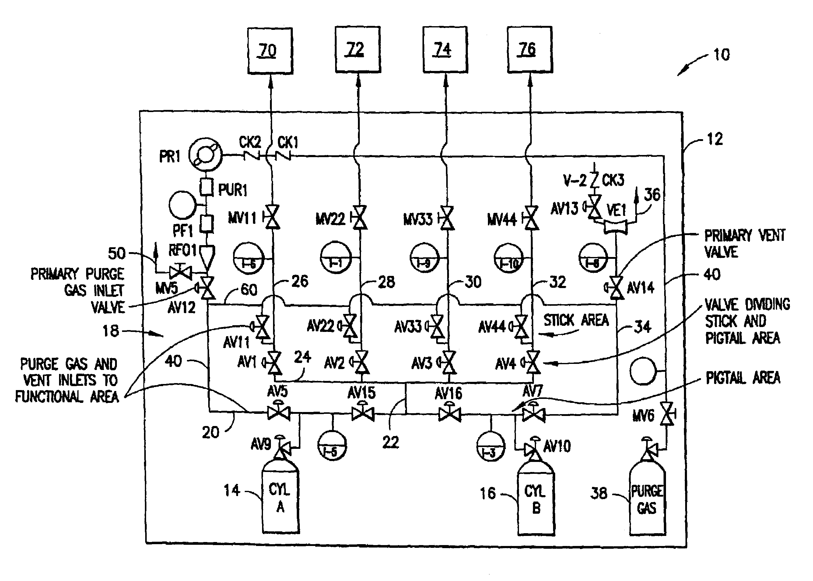
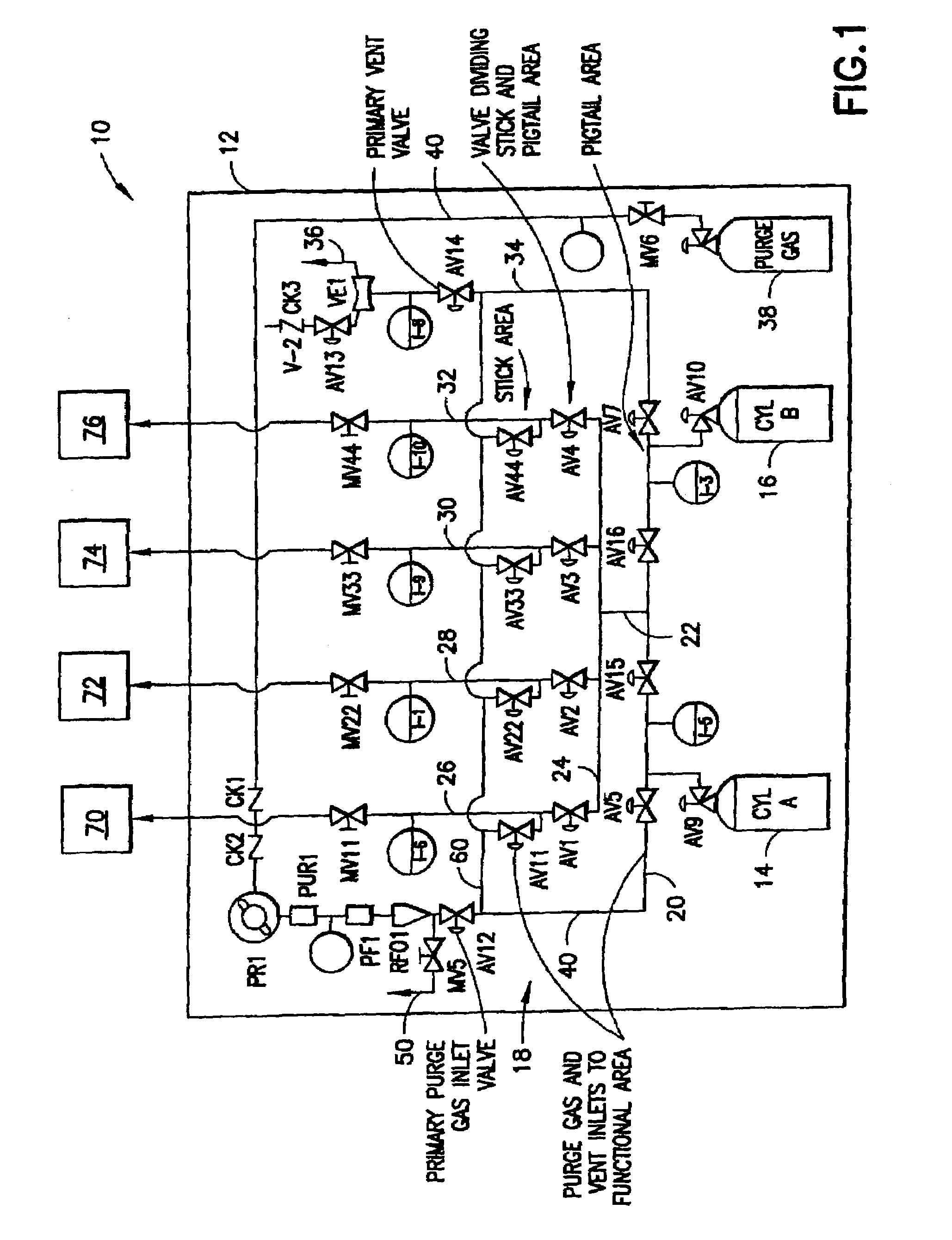
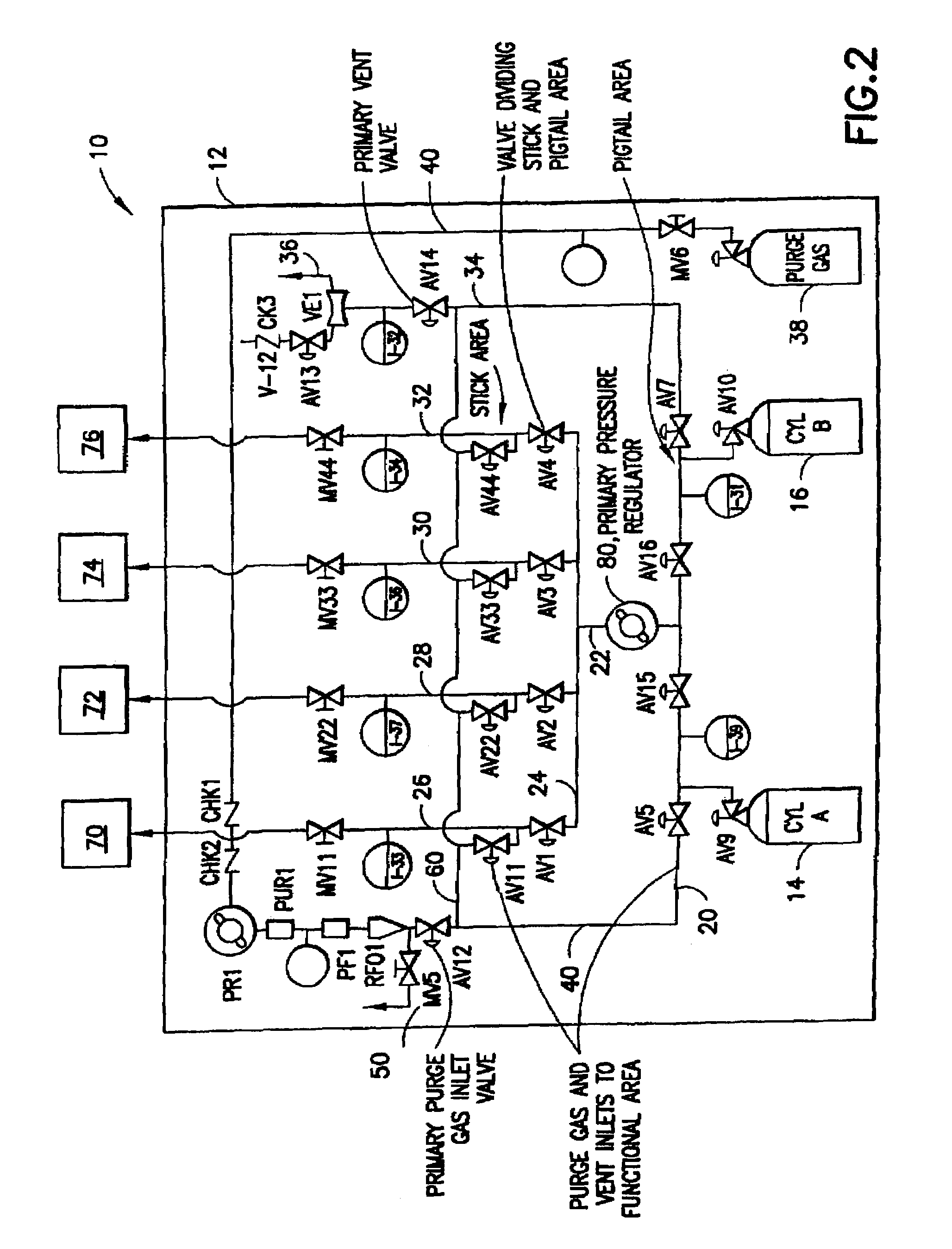
[0025]The present invention embodies a departure from conventional design of gas cabinets, and utilizes an integrated valved manifold in connection with sources of vacuum and purge gas, and flow circuitry including the integrated valved manifold, with such flow circuitry being coupled with one or more gas storage and dispensing vessels, and wherein the flow circuitry includes suitable valve, regulator and flow monitoring and control devices for enabling independent control of flow circuitry sections servicing respective ones of multiple semiconductor manufacturing tools.

[0026]In such gas cabinet, the provision of the integrated valved manifold provides the gas cabinet with the capability to service multiple semiconductor manufacturing tools, in the same functional manner as a prior art gas cabinet coupled with a separate dedicated valve manifold box (VBM).

[0027]Additionally, the gas cabinet of the invention has the ability to evacuate and purge specific sections of the gas flow circ...


PUM


Abstract

A gas cabinet including an enclosure containing at least one gas supply vessel and flow circuitry coupled to the gas supply vessel(s). The flow circuitry is constructed and arranged to flow dispensed gas from an on-stream gas supply vessel to multiple sticks of the flow circuitry, with each of the multiple sticks being joined in gas flow communication to a respective gas-utilizing process unit. The flow circuitry is valved to enable sections of the flow circuitry associated with respective ones of the multiple sticks to be isolated from other sections of the flow circuitry, so that process gas can be flowed to one or more of the sticks, while other sticks are being evacuated and purged, or otherwise are closed to dispensed gas flow therethrough.

Description

BACKGROUND OF THE INVENTION[0001]The present invention relates to a gas delivery system for delivering gas to a gas-utilizing process, e.g., for semiconductor manufacture. More specifically, the invention relates to a gas delivery system with an integrated valved manifold useful for sub-atmospheric as well as super-atmospheric pressure applications.DESCRIPTION OF THE RELATED ART[0002]In current semiconductor industry practice, gases are conventionally delivered from gas delivery systems including gas cabinets. Gas cabinets typically are fabricated as enclosure structures having doors or access panels, containing a supply of semiconductor manufacturing gas, e.g., in the form of one or more gas storage and dispensing vessels, together with associated piping, manifolding, valves, instrumentation, controllers (central processing units, programmable logic controllers, automatic shut-off systems, etc.) and outputs (alarms, screen displays, etc.), arranged for dispensing and delivery of ga...

Claims


Application Information

Patent Timeline
Patent Type & Authority Patents(United States)
IPC IPC(8): G05D7/00B01DF17C13/04
CPCF17C13/04F17C2205/0142F17C2205/0146F17C2205/0326F17C2205/0329F17C2205/0335F17C2270/0518F17C2223/033F17C2223/035F17C2223/036F17C2223/038F17C2227/0114F17C2227/044F17C2205/0338Y10T137/0396Y10T137/0419Y10T137/4259Y10T137/7043Y10T137/87877
Inventor WODJENSKI, MICHAEL J.DIETZ, JAMES A.
Owner ADVANCED TECH MATERIALS INC
Why Eureka
Try Eureka