Gas bag module

a technology of gas bag and bag body, which is applied in the direction of steering control, printed circuit aspects, electrical apparatus, etc., can solve the problems of increasing the number of cables for connecting the operating elements to the vehicle electronics, the spatial arrangement of the cabling and contacts for activating electrical function elements, and the space requirements, so as to save the installation space of the usual cable leads and plug connectors, and the effect of cost-effectiveness

Inactive Publication Date: 2006-05-30
TRW AUTOMOTIVE SAFETY SYST
View PDF9 Cites 16 Cited by
  • Summary
  • Abstract
  • Description
  • Claims
  • Application Information

AI Technical Summary

Benefits of technology

[0006]The generator support of the gas bag module according to the present invention can therefore be configured in a simple manner as a three-dimensional, injection-molded circuit substrate or molded interconnected device. Thus a multiplicity of familiar and cost-effective manufacturing methods are available. The conducting tracks of the printed circuit formed on the generator support take on the function of the conventional cabling. Therefore, on the one hand, weight can be reduced and, on the other hand, installation space for the usual cable leads and plug connectors is saved. In order that the printed circuit that is applied to the generator support be connected to the vehicle electronics, only a single plug-in circuit board is required, as a result of which the placement of cables in the steering wheel is made significantly simpler. Various switching elements for activating electrical function elements via the vehicle electronics can be connected to the printed circuit on the generator support, the switching elements being comfortably accessible to the driver as a result of the arrangement of the switching elements in the steering wheel.
[0007]Finally, the present invention makes it possible to additionally simplify the design of the multifunctional switches that are integrated in the steering wheel, because the generator support that must be there in any case can be used as a base for the switching elements. In this way, a simple and cost-effective design of a multifunctional switch that is integrated in the steering wheel is achieved.
[0011]The printed circuit and therefore the various multifunctional switches that are connected to the printed circuit can be connected to the vehicle electronics via a simple, soldered plug connection. In this way, the cabling of the individual switching elements to the vehicle electronics is significantly simplified.

Problems solved by technology

However, due to the space requirements for the gas bag module, problems arise with respect to the spatial arrangement of the cabling and contacts for activating electrical function elements such as an electrical horn.
However, in this way the number of cables for connecting the operating elements to the vehicle electronics grows, along with the space requirements.

Method used


Image

  • Gas bag module
  • Gas bag module
  • Gas bag module

Examples


Embodiment Construction

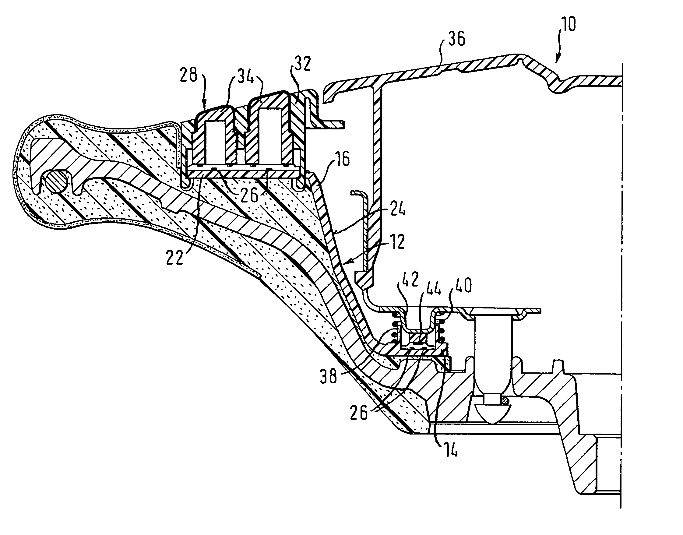
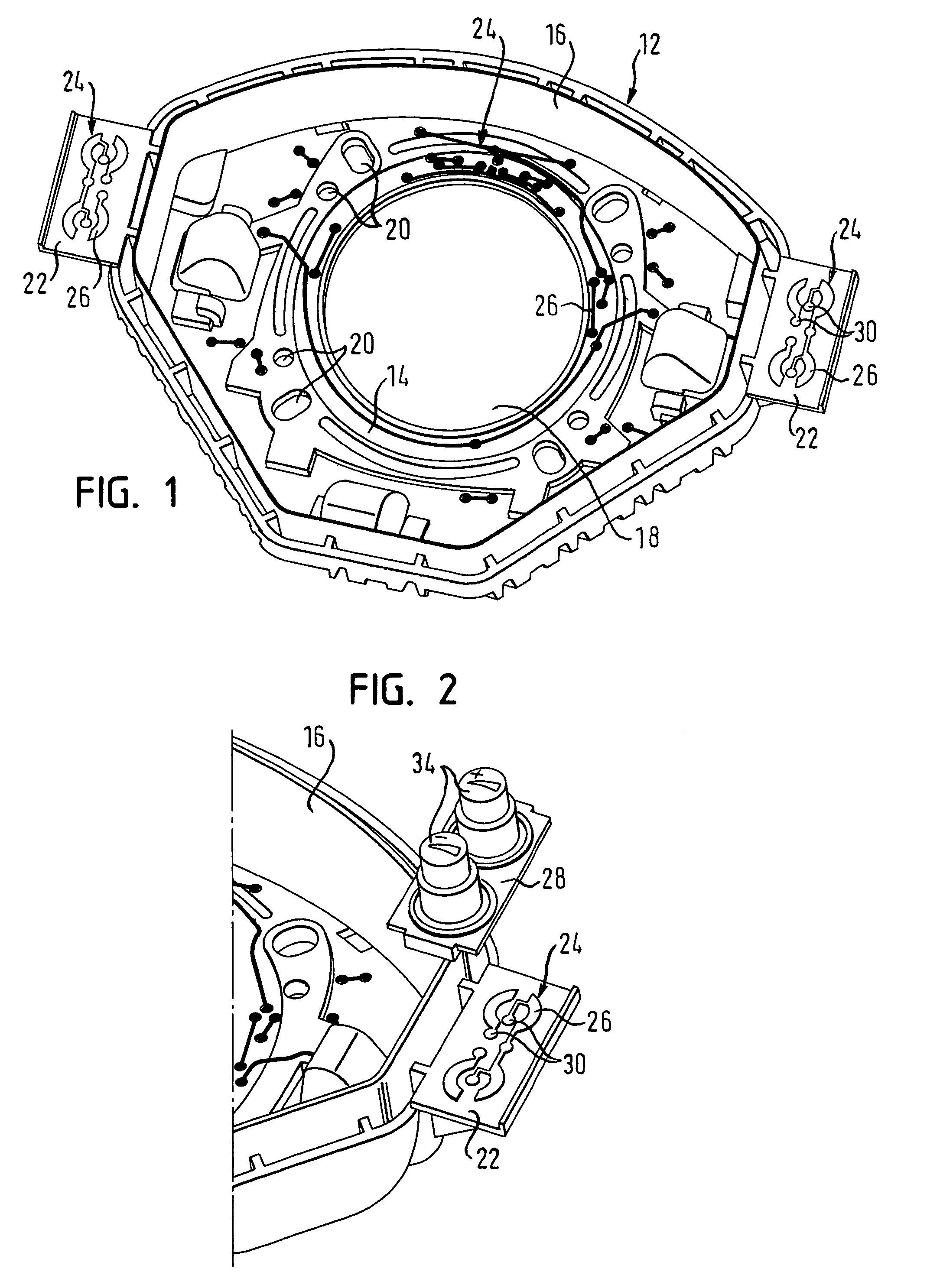
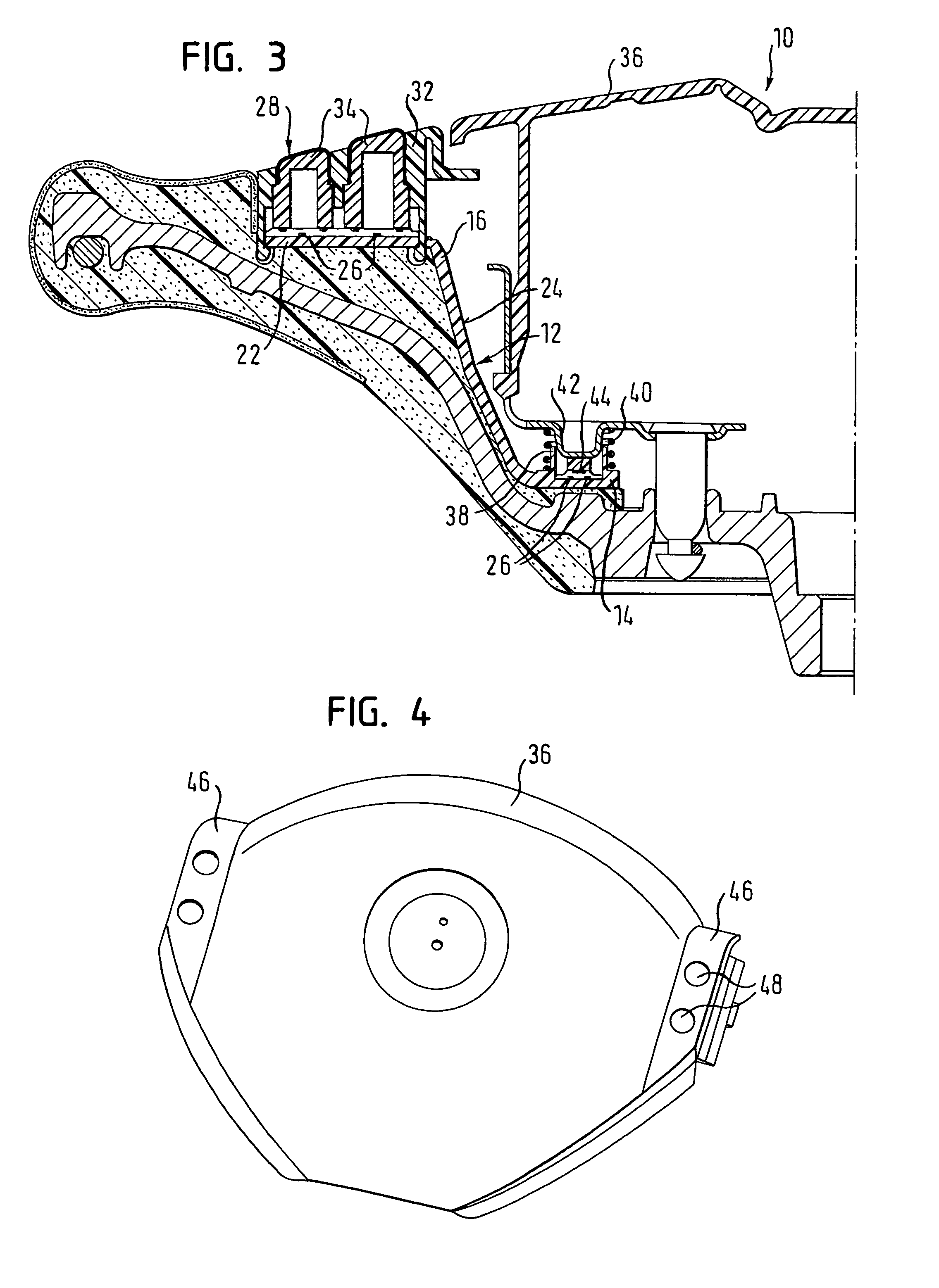
[0019]FIG. 1 depicts generator support 12 of a gas bag module (not shown here) which is designed for installation in the steering wheel of a motor vehicle. Generator support 12 is made of plastic in an injection molding process. It has a generally pot-shaped design, having a base 14 and a circumferential side wall 16 that proceeds from base 14. Base 14 has a central opening 18 for accommodating a gas generator (not shown). In addition, further openings 20 are introduced in the base, serving, for example, to attach the gas generator to generator support 12.

[0020]On two opposite positions of side wall 16, a respective plate-shaped section 22 is integrally formed, projecting outwardly. On base 14, a printed circuit 24 having conducting tracks 26 is applied by metal deposition, the printed circuit extending as far as to plate-shaped section 22.

[0021]As is depicted in FIG. 2 in a detail view, plate-shaped section 22 having conducting tracks 26 of printed circuit 24, applied thereon, func...


PUM


Abstract

A Gas bag module for use in a vehicle occupant restraint device has a plastic generator support. On the generator support a printed circuit is formed by metal deposition. For activating an electrical function element, the printed circuit cooperates with a switching element that is arranged on a section of the generator support.

Description

TECHNICAL FIELD[0001]The present invention relates to a gas bag module for use in a vehicle occupant restraint device having a plastic generator support.BACKGROUND OF THE INVENTION[0002]Gas bag modules are a component part of vehicle occupant restraint systems and can be arranged in the steering wheel, for example, for the protection of the driver. However, due to the space requirements for the gas bag module, problems arise with respect to the spatial arrangement of the cabling and contacts for activating electrical function elements such as an electrical horn. In addition, operating elements and switches for controlling the vehicle functions need to be easily accessible for the driver on or in the steering wheel, and if possible they should be configured as multifunctional elements. However, in this way the number of cables for connecting the operating elements to the vehicle electronics grows, along with the space requirements.[0003]In accordance with the so-called “floating horn...

Claims


Application Information

Patent Timeline
Patent Type & Authority Patents(United States)
IPC IPC(8): H01H9/00B60R21/2165
CPCB60Q1/0082B60Q5/003B60R21/2037B60R21/21658B62D1/046H05K1/0284H05K3/185H05K2203/107H05K3/381H05K2201/0236H05K2201/09118H05K2201/10053H05K2203/095H05K1/0373
Inventor HELMSTETTER, MATTHIASHIRZMANN, GUIDOHEIL, ANDREASSCHNEIDER, MICHAEL
Owner TRW AUTOMOTIVE SAFETY SYST
Why Eureka
Try Eureka