Linear oscillating actuator system

a technology of linear oscillating actuator and actuator, which is applied in the direction of electrical equipment, dynamo-electric machines, metal working equipment, etc., can solve the problems of lessening the output power of the actuator, unsatisfactory stator vibration, etc., and achieves the effect of minimizing torsion, minimizing thickness vibration, and increasing rigidity

Active Publication Date: 2006-05-30
MATSUSHITA ELECTRIC WORKS LTD
View PDF3 Cites 21 Cited by
  • Summary
  • Abstract
  • Description
  • Claims
  • Application Information

AI Technical Summary

Benefits of technology

[0004]Preferably, the output shaft is designed to project from the oscillator at a center of its thickness extending perpendicular to the linear path. Thus, a rotation moment about the output shaft is minimized to thereby minimize a torsion being applied to any mounting member responsible for movably supporting the oscillator to the stator assembly.
[0005]Also, the said oscillator and said balancer are preferably configured to have their respective mass centers aligned around the output shaft for the purpose of minimizing vibrations in the thickness direction.
[0006]The oscillator may be shaped from a plastic mold into which a magnetic yoke is entrapped in contact with the permanent magnet. In this case, the output shaft is secured to the magnetic yoke and is reinforced thereby to be given increased rigidity sufficient for minimizing the distortion of the output shaft.
[0007]Further, the oscillator and the balancer may be are interconnected by a mechanical link for assisting the reverse phase reciprocating relation therebetween. The mechanical link is connected to the oscillator at a point spaced upwardly of the permanent magnet along a length of the output shaft, reducing a possibility of bending the output shaft in its length with an attendant increase of energy transmission efficiency to the load.

Problems solved by technology

While driving the oscillator, the stator assembly is subject to counter vibrations, causing unpleasant stator vibrations felt by a user and eventually lessening the output power of the actuator.

Method used


Image

  • Linear oscillating actuator system
  • Linear oscillating actuator system
  • Linear oscillating actuator system

Examples


Embodiment Construction

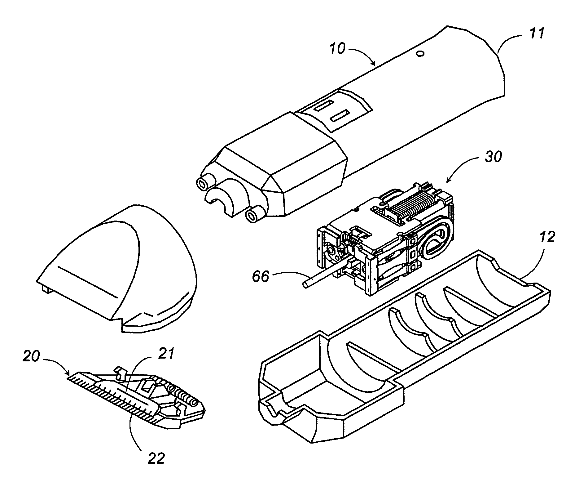
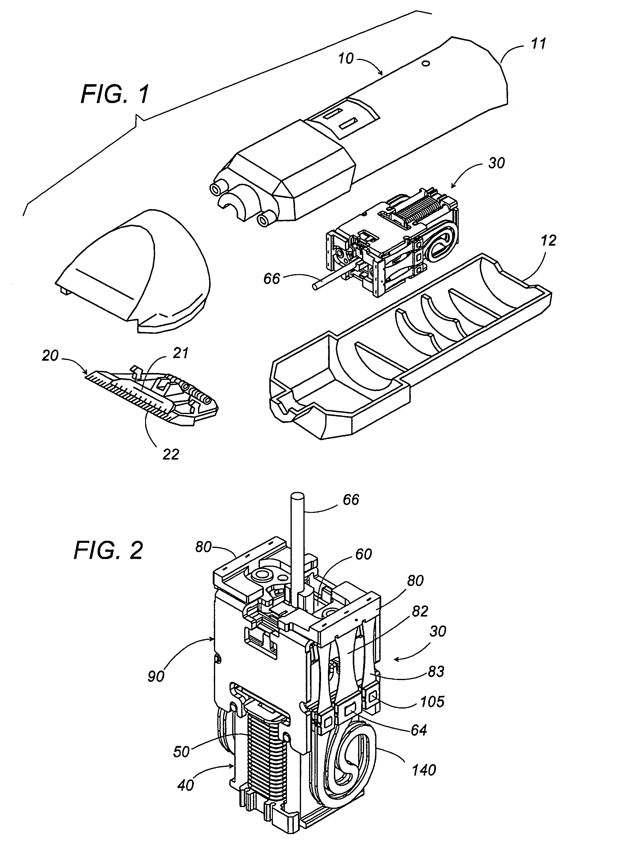
[0020]Now referring to FIG. 1, there is shown a hair cutter as one typical example which utilizes a linear oscillating actuator system of the present invention. The hair cutter includes a housing 10 composed of halves 11 and 12 to accommodate an actuator 30, and a cutter block 20 composed of a movable cutter 21 and a stationary cutter 22 fixed to the housing 10. The actuator 30 has an output shaft 66 which is connected to the movable cutter 21 for reciprocating it relative to the stationary cutter 22 for cutting hairs therebetween.

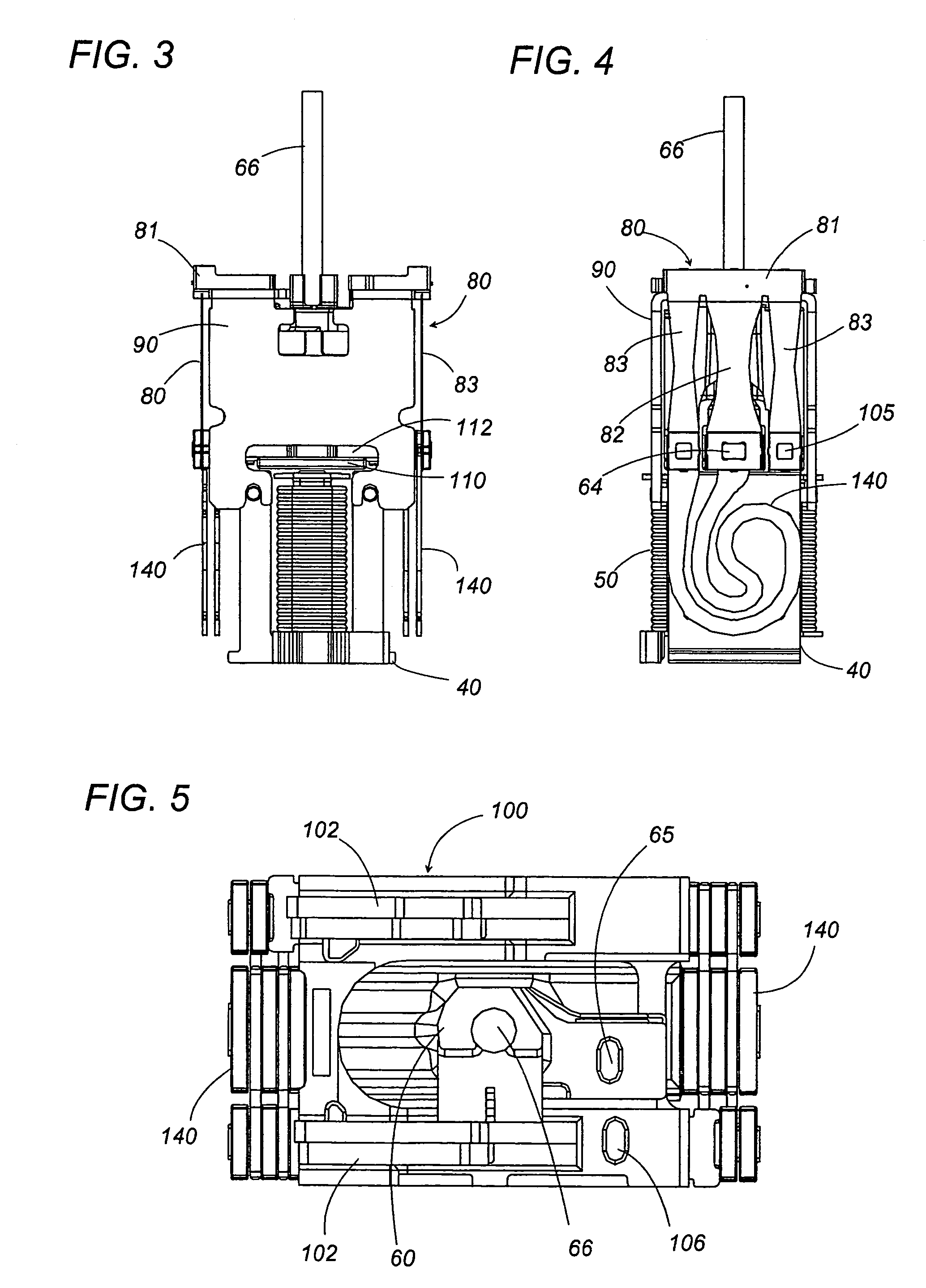
[0021]As best shown in FIGS. 2 to 6, the actuator 30 is basically composed of a stator assembly 40 carrying an electromagnet 50, and an oscillator 60 carrying a permanent magnet 70 as well as the output shaft 66. The electromagnet 50 includes an E-shaped stator 51 having a center core 52 and a pair of side cores 53. A coil 54 is wound around the center core 52 to magnetize pole ends at the respective upper ends of the center and side cores to opposite pola...


PUM


Abstract

A linear oscillating actuator system which is capable of canceling out the stator vibrations for driving a load with a minimum of vibrations. The system includes an oscillator carrying a permanent magnet as well as an output shaft for connection to the load. A stator assembly is incorporated within a housing and is configured to movably support the oscillator and to carry an electromagnet. The electromagnet generates a magnetic field which interacts with the permanent magnet to reciprocate the oscillator relative to the stator assembly in a linear path. A balancer is added to the system for canceling out undesired stator vibrations. The balancer are commonly supported to the stator assembly to be driven thereby in parallel with the oscillator. The balancer is configured to have a mass generally equal to that of the oscillator and to be devoid of any output member. Thus, the oscillator and the balancer are driven in a counter reciprocating manner, thereby keeping the stator assembly free from counter-vibrations and therefore driving the output shaft with a maximum output power.

Description

TECHNICAL FIELD[0001]The present invention is directed to a linear oscillating actuator system provided with a balancer for driving a load with reduced stator vibrations.BACKGROUND ART[0002]Japanese Utility Model Publication JP53-42235 discloses an oscillating actuator system having a single output for imparting a reciprocating motion to a load, i.e., the inner cutter of a dry shaver. The actuator includes a stator assembly including an electromagnet and an oscillator held in a closely spaced relation with the stator assembly. The oscillator includes a permanent magnet that is magnetically coupled to the electromagnet for driving the oscillator in response to an alternating current supplied to the electromagnet. While driving the oscillator, the stator assembly is subject to counter vibrations, causing unpleasant stator vibrations felt by a user and eventually lessening the output power of the actuator.DISCLOSURE OF THE INVENTION[0003]In view of the above problem, the present invent...

Claims


Application Information

Patent Timeline
Patent Type & Authority Patents(United States)
IPC IPC(8): H02K33/00B26B19/28H02K7/04H02K7/06H02K33/02H02K33/06H02K33/10H02K33/16H02K35/00
CPCB26B19/282B26B19/288H02K33/16H02K33/06H02K7/04
Inventor KOBAYASHI, NOBORUMORIGUCHI, MASASHINISHINAKA, TAKAHIROYABUUCHI, HIDEKAZUMOTOHASHI, RYO
Owner MATSUSHITA ELECTRIC WORKS LTD
Why Eureka
Try Eureka