Circuit arrangement with a linear variable differential transformer (LVDT) as a displacement sensor or force sensor

a technology of linear variable differential transformer and displacement sensor, which is applied in the direction of movable seats, process and machine control, instruments, etc., can solve the problems of inability to use measurement principle, increase the cost of materials, so as to achieve the effect of double the sensitivity of measuremen

Inactive Publication Date: 2006-05-30
SIEMENS AG
View PDF8 Cites 16 Cited by
  • Summary
  • Abstract
  • Description
  • Claims
  • Application Information

AI Technical Summary

Benefits of technology

[0008]The invention develops the generic circuit arrangement such that the temperature may be measured as accurately as possible with minimal cost.
[0010]According to another embodiment of the invention, the current through the primary coil has a trapezoidal characteristic with correspondingly high rising edge and falling edge values. The control circuit is thus configured such that sampling values of a rectangular voltage picked up on the primary coil and also of a voltage proportional to the current through the primary coil, are taken at times when the trapezoidal current has a constant characteristic. This causes the resistance value of the primary coil to be determined if just one direct current flows through the primary coil, and therefore its inductance does not affect the measurement result.
[0013]In a further embodiment, the sampling values are determined in both the first and second halves of the period and the difference values formed from the sampling values from the first half of the period and from the sampling values from the second half of the period are used as measurement values. This doubles the sensitivity of the measurement. Furthermore, common-mode interferences are eliminated by the difference formation.
[0015]Triggering the primary coil of the transformer using a current with a trapezoidal characteristic enables bipolar rectangular voltages to be picked up on the secondary coils. The amplitude of these rectangular voltages is proportional to the displacement of the transformer core during the phase position of these rectangular voltages and shows the direction in which the displacement occurs. The rectangular voltages are bipolar relative to a reference voltage, which ideally corresponds to half of the supply voltage. If the core is located in a position midway between the two secondary coils, which—in an application to determine seated weight in a vehicle—corresponds to a situation in which the seat is not occupied, the amplitudes and phases of the two secondary coil output voltages are of equal size and their difference is zero accordingly. If the core is displaced, one secondary coil output voltage is higher and the other correspondingly lower. Therefore, in order to determine any deviation in the core from this midway position, the difference between the two is formed since this enables the sensitivity to be increased. Moreover, additional interference signals which are superimposed on the two output voltages are eliminated.
[0019]In another advantageous embodiment, the rectangular voltage generation circuit is formed with a first resistor, whose first terminal is connected to a third voltage source and whose second terminal is connected to the output of the rectangular voltage generation circuit, and with a second resistor, whose first terminal is connected to a fourth voltage source and whose second terminal is connected to the output of the rectangular voltage generation circuit via a switch controllable from a control circuit, the voltages of the third and the fourth voltage source following the relationshipU3−Uref=Uref−U4and Uref being a reference voltage, which—for example—may be half the value of the supply voltage. If the third and the fourth voltage source are configured as controllable, variable voltage sources, the amplitude of the rectangular voltage—and thus the edge steepness of the triangular output voltage of the integration circuit—can easily be adjusted by triggering the two voltage sources through the control circuit.
[0022]The formation of the difference between a positive and a negative sampling value produces a measurement value with double amplitude, resulting in a two-fold increase in the sensitivity of the measurement device. In addition, any direct voltage offsets present are eliminated by the difference formation.

Problems solved by technology

The use of additional thermal detectors, however, requires additional expenditure on materials and is therefore less cost-effective.
However, in a circuit arrangement with a transformer, whose primary coil has a triangular voltage applied to it and in which a triangular voltage should also be present on the secondary side, this measurement principle cannot be used since the coil cannot reach saturation.

Method used


Image

  • Circuit arrangement with a linear variable differential transformer (LVDT) as a displacement sensor or force sensor
  • Circuit arrangement with a linear variable differential transformer (LVDT) as a displacement sensor or force sensor
  • Circuit arrangement with a linear variable differential transformer (LVDT) as a displacement sensor or force sensor

Examples


Embodiment Construction

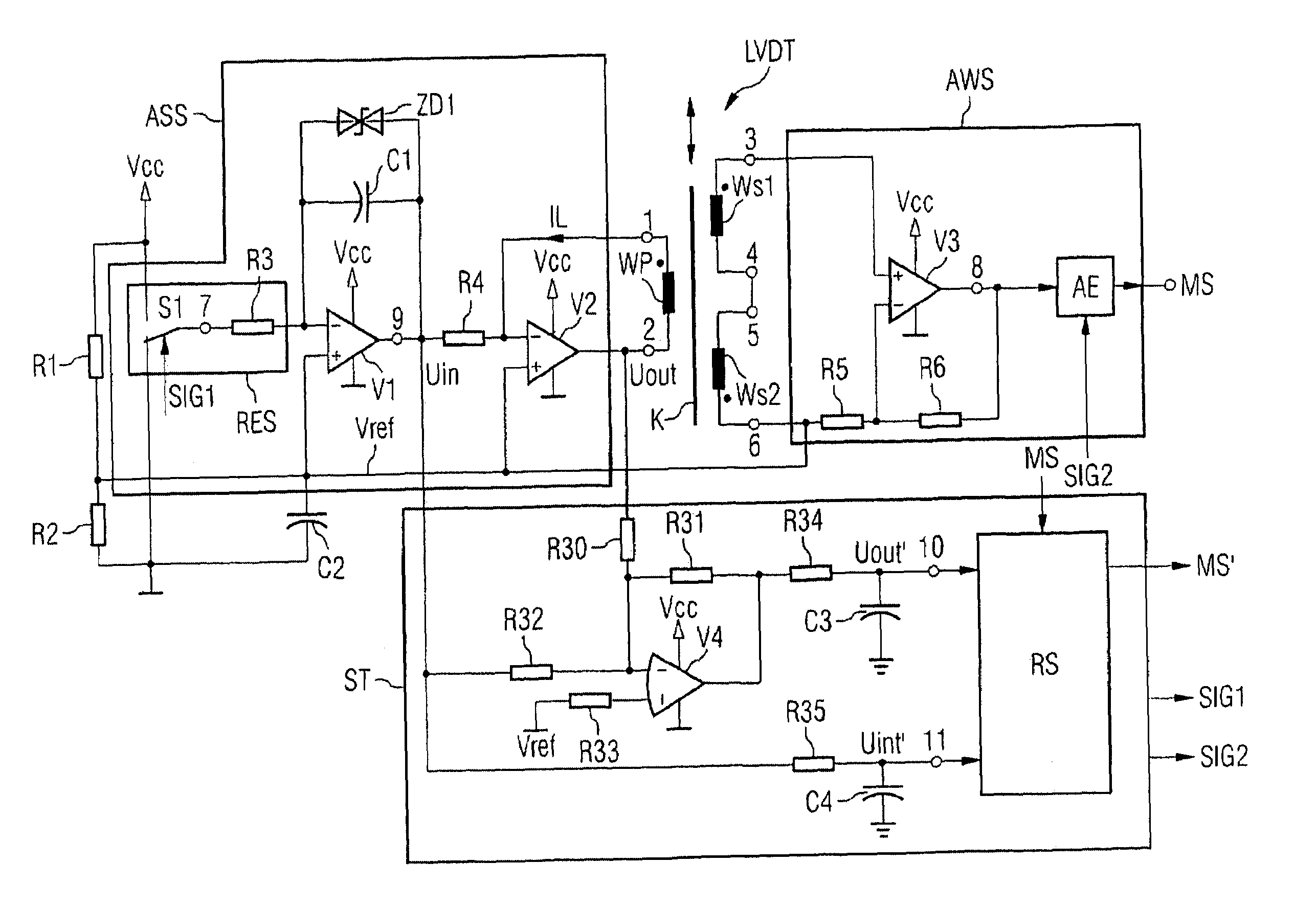
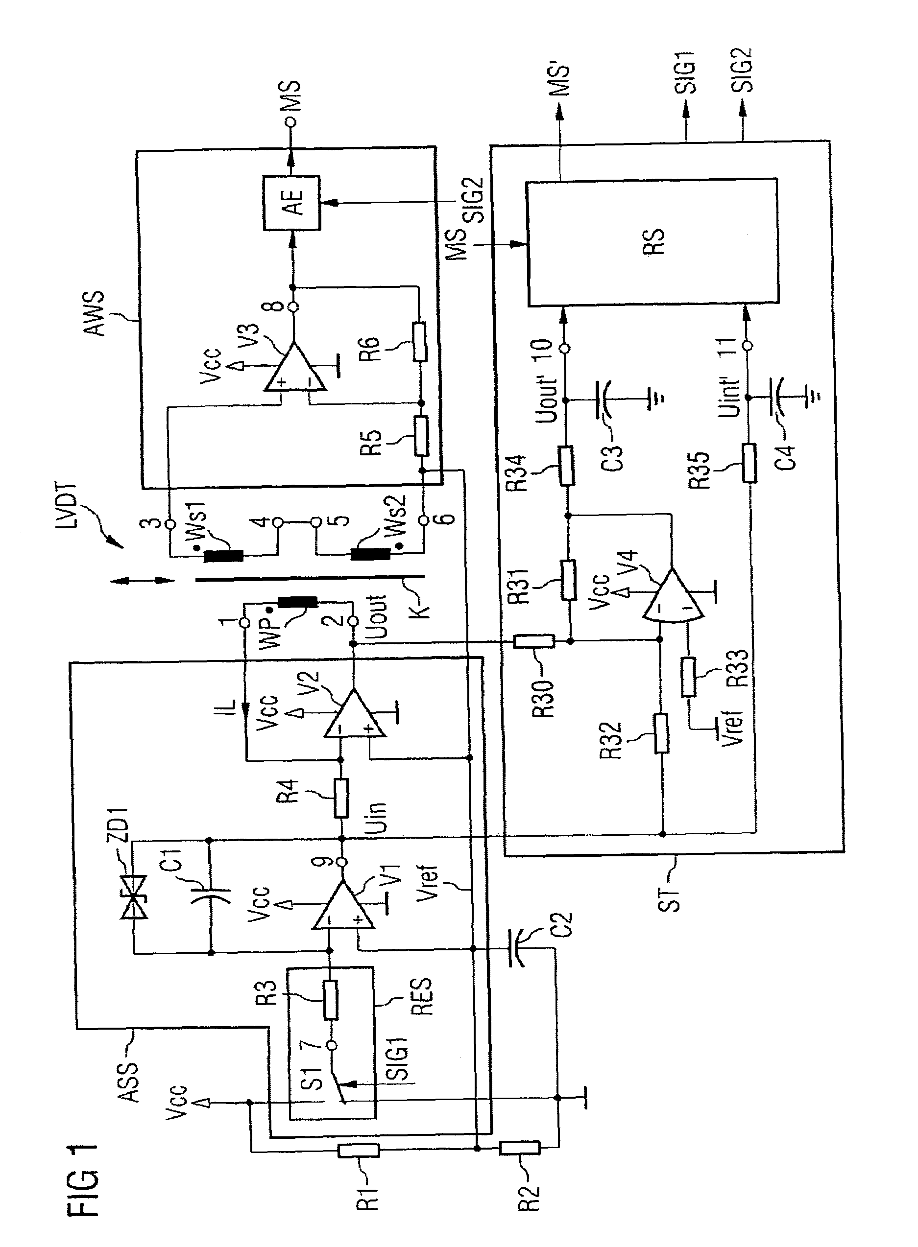
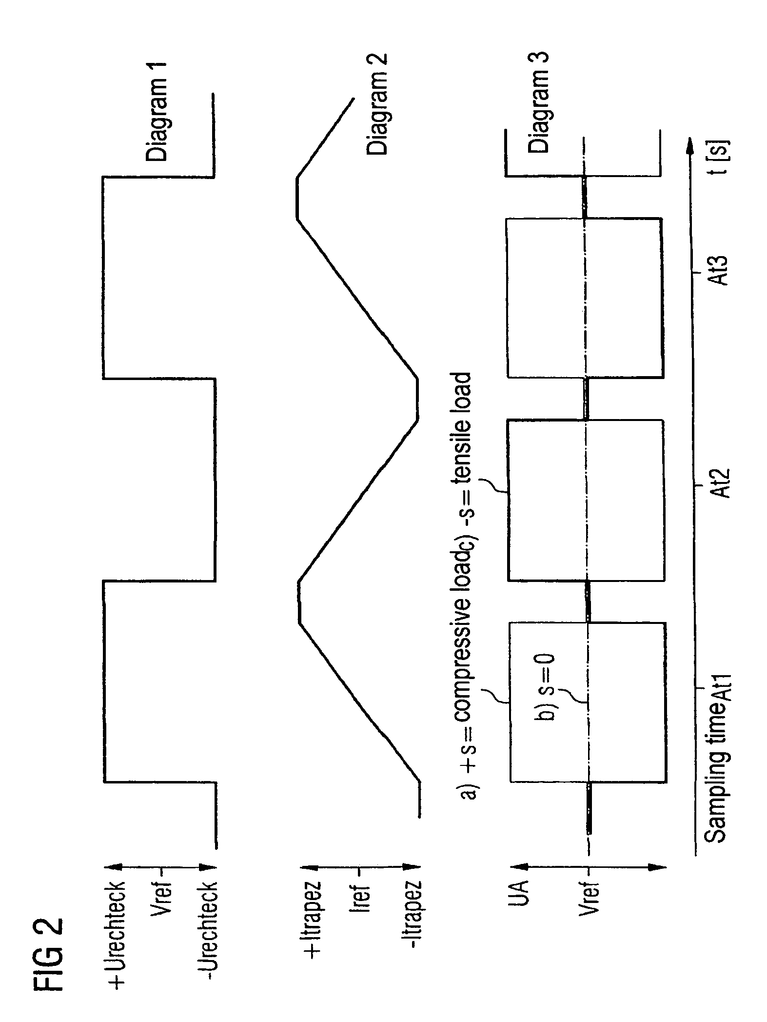
[0034]FIG. 1 shows a linear variable differential transformer (LVDT), which is formed with a primary coil Wp and two secondary coils Ws1, Ws2. The primary coil Wp is magnetically coupled to the secondary coils Ws1, Ws2 via a core K. The secondary coils Ws1, Ws2 are connected in series such that the difference between the voltages at the individual secondary coils Ws1 and Ws2 can be picked up at the free ports 3 and 6. The core K is moveable and, for the preferred application field, may be coupled with a driver's seat using a method that is not illustrated, so that—in the event of a compressive or tensile load on the seat—the core may move accordingly between the coils of the linear variable differential transformer (LVDT). If the core K is located in a position midway between the two secondary coils Ws1, Ws2, the voltage that may be picked up at ports 3 and 6 is equal to 0.

[0035]The primary coil Wp is triggered at its ports 1, 2 by a selection circuit ASS with a current IL with trap...


PUM

PropertyMeasurementUnit
temperatureaaaaaaaaaa

Abstract

In a circuit arrangement having a linear variable differential transformer as a displacement sensor or force sensor, having a selection circuit which is connected to the primary coil of the transformer and which provides an output current for triggering the primary coil, and having an analysis circuit which is connected to the secondary coils of the transformer and which provides a message signal, a control circuit used for triggering the selection circuit and the analysis circuit and for processing the measurement signal provided by the analysis circuit is connected to the primary coil in order to calculate the temperature of the circuit arrangement, and is configured such that it determines the temperature-dependent ohmic resistance of the primary coil and calculates from it the temperature and corrects accordingly the measurement signal provided by the analysis circuit.

Description

CLAIM FOR PRIORITY[0001]This application claims the benefit of priority to German Application No. 10313022.5, filed in the German language on Mar. 24, 2003 and German Application No. 10313021.7, filed in the German language on Mar. 24, 2003, the contents of which are hereby incorporated by reference.TECHNICAL FIELD OF THE INVENTION[0002]The invention relates to a circuit arrangement having a linear variable differential transformer as a displacement or force sensor.BACKGROUND OF THE INVENTION[0003]A generic circuit arrangement is known from U.S. Pat. No. 5,777,468 A. When such a circuit arrangement is used to determine the weight of a person sitting in a driver's seat—i.e. the force being exerted upon the driver's seat—the amount of displacement of the driver's seat caused by the exertion of force or by the weight of the person is measured and converted into an electrical signal. In such an application it is desirable not only for the person's weight to have a sufficiently high reso...

Claims


Application Information

Patent Timeline
Patent Type & Authority Patents(United States)
IPC IPC(8): G01B7/14B60N2/02G01D3/036G01D5/22G01L1/14
CPCB60N2/0244G01L1/14G01D5/2291G01D3/036
Inventor SWART, MARTEN
Owner SIEMENS AG
Why Eureka
Try Eureka