Controller for a security system

a technology for security systems and controllers, applied in control systems, frequency-division multiplexes, instruments, etc., can solve problems such as the inability to permanently install inventive systems, the inability to drill holes for hardwiring, and the inability to install security systems in apartments. achieve the effect of high reliability

Inactive Publication Date: 2006-05-30
LIFESHIELD LLC
View PDF117 Cites 199 Cited by
  • Summary
  • Abstract
  • Description
  • Claims
  • Application Information

AI Technical Summary

Benefits of technology

[0011]The present invention is a highly reliable system and method for constructing a security system for a building using a novel approach to designing RFID read

Problems solved by technology

Second, homeowners may purchase the inventive system at a home improvement chain, self-install the system, and contract for alarm monitoring from an alarm services company.
Presently, very few security systems are in

Method used


Image

  • Controller for a security system
  • Controller for a security system
  • Controller for a security system

Examples


Embodiment Construction

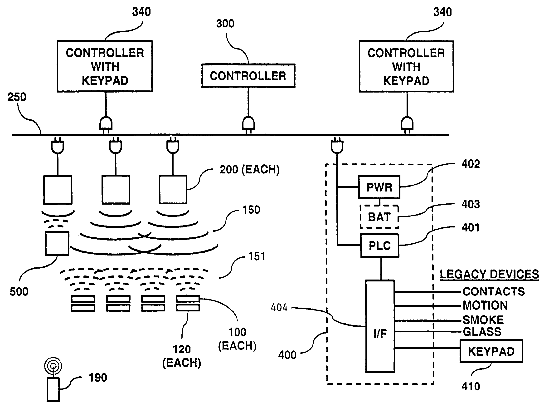
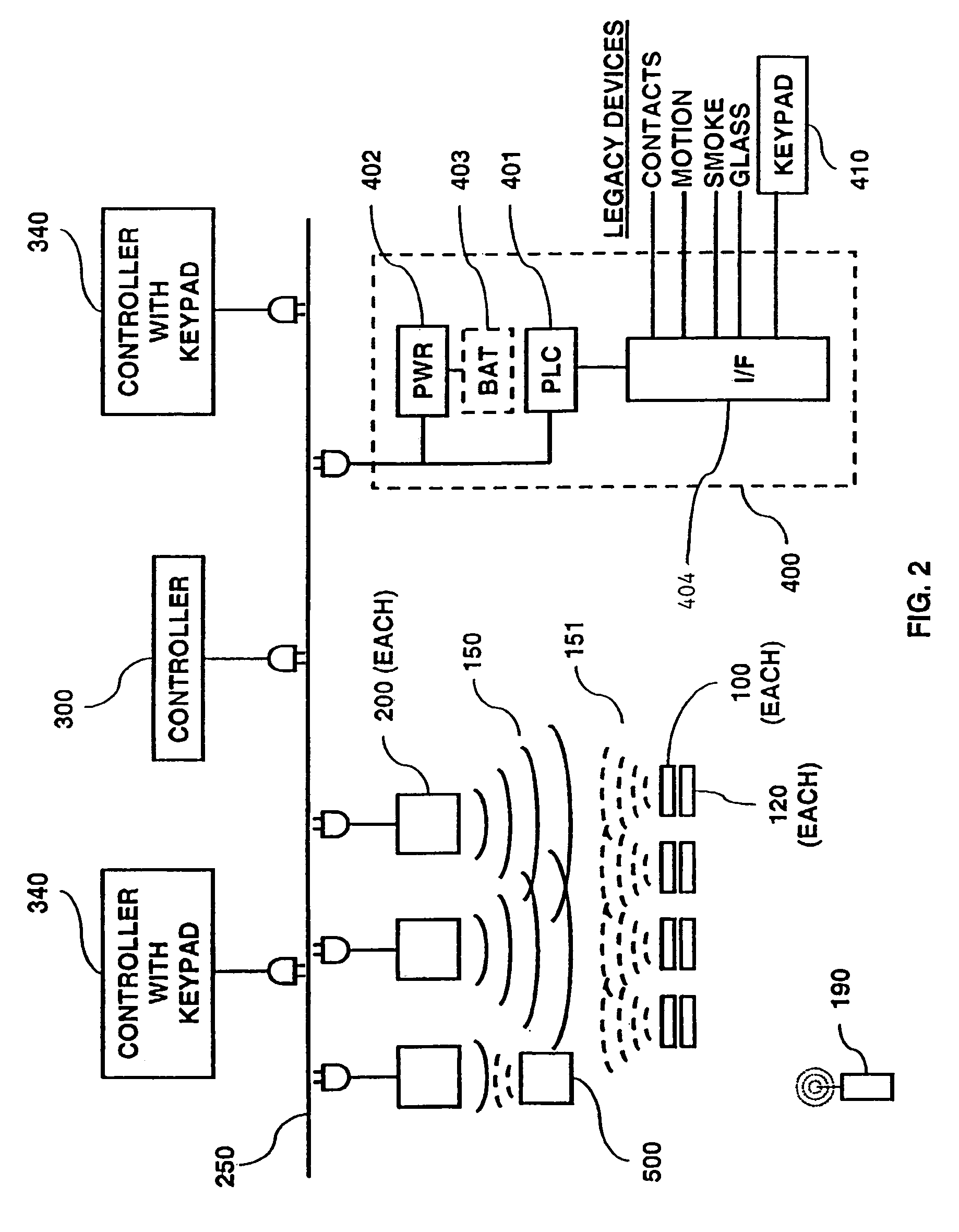
[0042]The present invention is a highly reliable system and method for constructing a security system for use in a building, such as a commercial building, single or multifamily residence, or apartment. The security system may also be used for buildings that are smaller structures such as sheds, boathouses, other storage facilities, and the like.

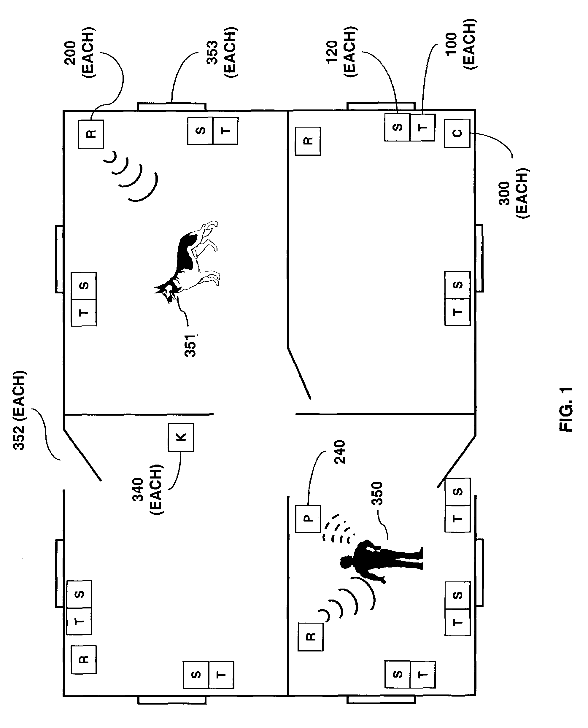
[0043]There are 4 primary parts to the security system: an intrusion sensor 120, an RFID transponder 100, an RFID reader 200, and a controller 300. FIG. 1 shows an example of the layout for a small house and FIG. 2 shows a general architecture of the security system. At each opening in the house, such as windows 353 and doors 352, for which monitoring is desired, an intrusion sensor 120 and RFID transponder 100 are mounted. In approximately each major room of the house, an RFID reader 200 is mounted. Each RFID reader 200 is in wireless communications with one or more RFID transponders 100. In general, each RFID reader 200 is responsible for ...


PUM


Abstract

A controller for use in a security system based upon RFID techniques. The controller can use power line carrier communications to communicate with other devices in the security system. The controller can use a modem or wireless module to connect to public networks. Multiple controllers can be used in a system, and the controllers can arbitrate to determine a master controller. The controller contains configuration data and tables that define the relationships between devices in the security system. The controller can receive communications from other devices in the system and can interface with legacy devices previously used with wired security systems. The controller can send messages based upon predetermined events, and can support a remote alerting function.

Description

CROSS REFERENCE TO RELATED APPLICATIONS[0001]This patent application is a continuation-in-part of U.S. application. Ser. No. 10 / 356,512, filed on Feb. 3, 2003, titled “RFID Based Security System,” by the inventor of the present application. This patent application is further cross referenced to the other following patent applications, filed even date herewith by the inventor of the present application: “Communications Control in a Security System,” U.S. application Ser. No. 10 / 366,320; “Device Enrollment in a Security System,” U.S. application Ser. No. 10 / 366,335; “RFID Transponder for a Security System,” U.S. application Ser. No. 10 / 366,317; and “RFID Reader for a Security System,” U.S. application Ser. No. 10 / 366,316.TECHNICAL FIELD[0002]The present invention relates generally to security systems and, more particularly, to RFID controllers as one component of such a security system.BACKGROUND OF THE INVENTION[0003]Security systems are described in numerous patents, and have been i...

Claims


Application Information

Patent Timeline
IPC IPC(8): G08B29/00G08B13/22
CPCG08B25/008
Inventor STILP, LOUIS A.
Owner LIFESHIELD LLC
Why Eureka
Try Eureka