Electrical installation comprising a decompression channel

a decompression channel and electrical installation technology, applied in the direction of substation/switching arrangement casings, non-enclosed substations, substations, etc., can solve the problem that it is not possible for hot gases or pressure waves to enter the other functional modules, and neither the installation nor the person is harmed or damaged in any way, and achieves reliable dissipation

Inactive Publication Date: 2006-05-30
SIEMENS AG
View PDF21 Cites 42 Cited by
  • Summary
  • Abstract
  • Description
  • Claims
  • Application Information

AI Technical Summary

Benefits of technology

[0007]The invention discloses dissipation of the high pressures and temperatures which occur during an arc discharge without posing a risk to persons and the installation, and to ensuring sufficient robustness even for the case of intensive arc discharges and their effects.
[0010]One advantageous embodiment of the invention provides for the pressure release duct to have a trapezoidal cross-sectional profile. The refinement in which the cross-sectional surface has a trapezoidal form firstly provides great robustness and, secondly, makes simple manufacture possible.
[0014]A further advantageous embodiment of the invention provides for the pressure release duct to have a pressure release opening to the exterior of the installation. The pressure wave and the gases produced are in this case either dissipated into a pressure- and temperature-resistant area, in which there are no people, or are directed outside via a chimney system. In this manner, reliable dissipation is ensured without posing any risk to the installation or people.
[0015]A further advantageous embodiment of the invention is for the pressure release duct to be connected to the exterior of the installation via an absorption element. The absorption element reduces both the temperature and the pressure to such an extent that the gases can be dissipated both into a pressure- and temperature-resistant area or via a chimney system to the outside and into the area directly surrounding the installation.
[0016]A further advantageous embodiment of the installation provides for the pressure release duct to have ventilation openings on its top surface which close in a pressure-tight manner in the event of a pressure surge occurring in the pressure release duct. This ensures that sufficient cooling air is dissipated from the installation for normal operation of the installation. In the event of an arc flashover with the occurrence of hot gases and high pressures, the ventilation openings are closed by means of valves and prevent the gases from escaping into the area surrounding the installation.

Problems solved by technology

In the event of an arc forming in one of these functional modules, the excess pressure produced by the air suddenly being heated and the hot gases are dissipated such that neither persons nor the installation are harmed or damaged in any way.
Pressure release ducts are usually provided for this purpose and are connected to the individual functional modules by means of a suitable valve system such that it is possible for the excess pressure and the hot gases to be dissipated from the affected functional module but at the same time such that it is not possible for the hot gases or a pressure wave to enter the other functional modules.
Then, the gases are dissipated from the installation via ventilation slots such that they are thereafter only slightly harmful.
With all of these solutions it is possible, however, for the pressure release duct having a rectangular cross section not to be suitable for loads in the case of particularly intensive arc flashovers.

Method used


Image

  • Electrical installation comprising a decompression channel
  • Electrical installation comprising a decompression channel
  • Electrical installation comprising a decompression channel

Examples


Embodiment Construction

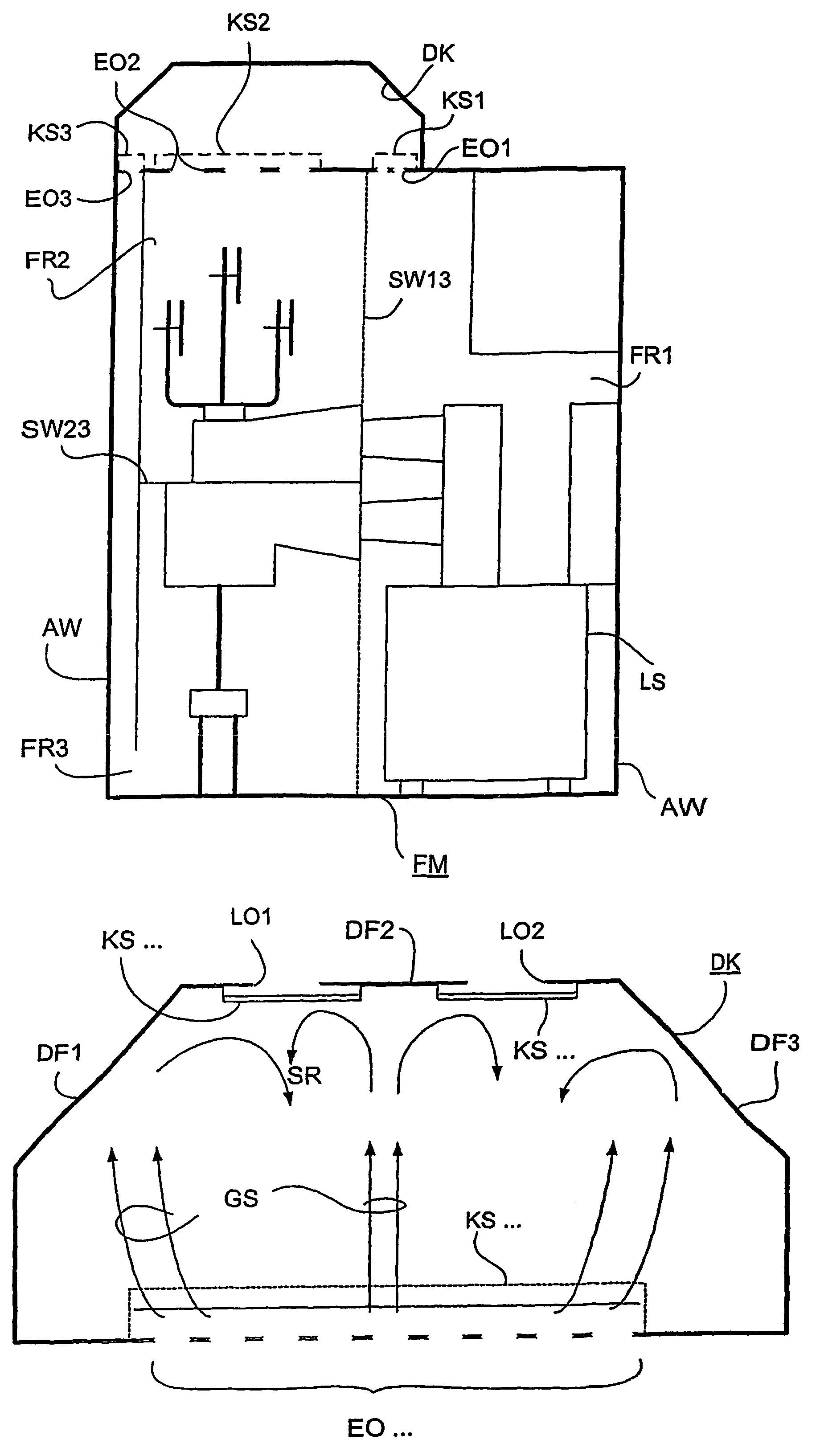
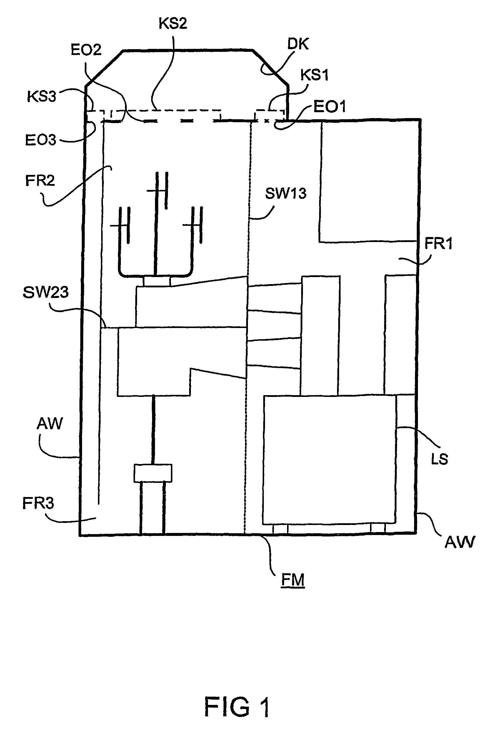
[0021]The functional module FM shown in FIG. 1 is divided up into a plurality of functional compartments FR 1, 2, 3. These compartments are separated from one another in a gas-permeable manner by partition walls SW 13, 23. In other designs, the partition walls SW . . . can also separate the individual functional compartments FR . . . from one another in a pressure-tight manner. The individual functional compartments FR . . . may be, for example, switching module compartments FR 1 having power breakers LS, connection compartments FR 3 or busbar compartments FR 2. The outer walls AW of the functional module FM shown are closed off in a pressure-tight manner both from the area surrounding the installation and from any further functional modules FM . . . which may be adjacent. In the exemplary embodiment shown, the inlet openings EO 1, 2, 3 to the pressure release duct DK are on the top face of the functional module FM. In this case, each functional compartment FR 1, 2, 3 has its own co...


PUM


Abstract

The invention relates to an electrical installation, especially a medium-voltage switchgear, comprising at least one encapsulated function module (FM), a decompression channel (DK) which is connected to said function module, and at least one inflow opening (EO . . . ) which connects the function module (FM) to the decompression channel (DK). The covering surface (DF 1,2,3) of the decompression channel (DK), opposite the inflow opening (EO . . . ), comprises at least one partial region which is obliquely oriented in relation to the inflow direction. Hot gases and high pressures produced during an accidental arc can thus be evacuated from the installation, without any risk to humans and buildings. Pressure channels are used, inter alia, in installations used in relation to medium-voltage technique for providing and distributing energy.

Description

CLAIM FOR PRIORITY[0001]This application is a national stage application of PCT / DE02 / 00933, which was published on Mar. 11, 2002, which claims the benefit of priority to German Application No. 10114742.2, filed Mar. 20, 2001.TECHNICAL FIELD OF THE INVENTION[0002]The invention relates to an electrical installation, and in particular to a medium-voltage switchgear assembly.BACKGROUND OF THE INVENTION[0003]For the protection of persons and of the installation, medium-voltage switchgear assemblies are provided with apparatuses for releasing pressure in order for it to be possible for the hot gases produced in the event of an arc flashover to be dissipated safety from the installation area. A number of functional modules are usually used for these switchgear assemblies, the functional modules being encapsulated with respect to one another and with respect to the atmosphere such that the effects of an explosion in the interior of the functional module cannot spread to the area surrounding...

Claims


Application Information

Patent Timeline
Patent Type & Authority Patents(United States)
IPC IPC(8): H02B7/06H02B1/26H02B13/025
CPCH02B13/025
Inventor EISELT, MARTINMAHN, GILDOMILBICH, ACHIM
Owner SIEMENS AG
Why Eureka
Try Eureka