
Non-volatile ferroelectric cell array block having hierarchy transfer sensing architecture

a technology of transfer sensing and ferroelectric cell array blocks, which is applied in the direction of information storage, static storage, digital storage, etc., can solve problems such as difficult realization, and achieve the effects of reducing layout area, improving circuit structure, and improving read and write stably

Inactive Publication Date: 2006-05-30
SK HYNIX INC
View PDF1 Cites 3 Cited by
  • Summary
  • Abstract
  • Description
  • Claims
  • Application Information

AI Technical Summary

Benefits of technology

[0008]It is, therefore, an object of the present invention to provide a non-volatile ferroelectric cell array block with an improved circuit structure, whereby a cell data can be read and written more stably even with a small cell capacitance and a layout area can be reduced.

Problems solved by technology

Although the bit line capacitance should be reduced for a memory with a small cell capacitance to operate more stably, it is not easy to realize this especially in the case of a high integration memory.

Method used


Image

  • Non-volatile ferroelectric cell array block having hierarchy transfer sensing architecture
  • Non-volatile ferroelectric cell array block having hierarchy transfer sensing architecture
  • Non-volatile ferroelectric cell array block having hierarchy transfer sensing architecture

Examples


first embodiment

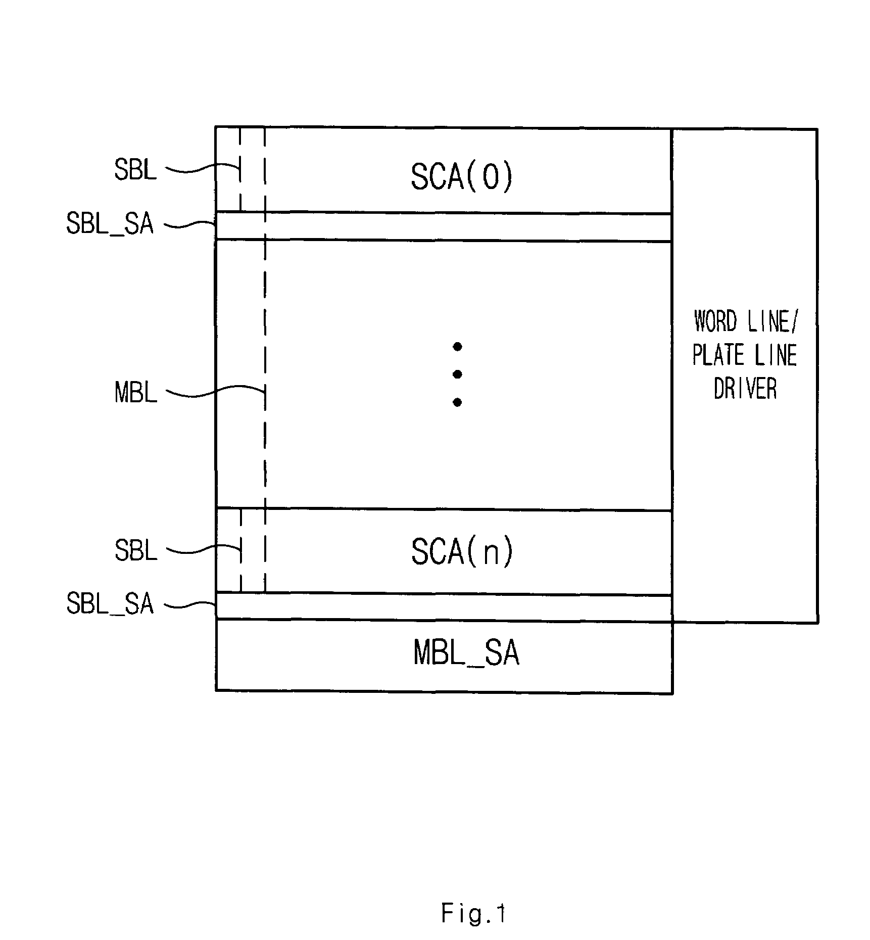
[0025]FIG. 1 is a schematic diagram of a non-volatile ferroelectric cell array block according to the present invention.

[0026]As shown in FIG. 1, the cell array block includes a plurality of sub cell arrays SCA(0)–SCA(n), each bit line having a hierarchy bit line architecture composed of a main bit line MBL and sub bit lines SBL. The sub bit line SBL is provided to each sub cell array SCA(0)–SCA(n), while the main bit line MBL is shared by the sub cell array SCA(0)–SCA(n), being selectively connected with the sub bit lines SBL. Since the sub bit line SBL are separated from the main bit line MBL, the capacitance of each sub bit line SBL is independent of the capacitance of the main bit line MBL. Thus, it is possible to reduce the capacitance of a bit line where cell sensing charge is transferred. A sensing voltage of a sub bit line SBL in a respective sub cell array SCA(0)–SCA(n) is amplified while the main bit line MBL is disconnected from the sub bit line and the amplified voltage ...

second embodiment

[0052]FIG. 5 is a schematic diagram of a non-volatile ferroelectric cell array block in accordance with the present invention.

[0053]As shown in FIG. 5, the cell array block includes a plurality of upper sub cell array SCA(0)–SCA(n), a plurality of lower sub cell array SCA(10)–SCA(1n), a main bit line sense amp MBL_SA, and a word line / plate line driver.

[0054]The upper sub cell array SCA(0)–SCA(n) and the lower sub cell array SCA(10)–SCA(1n) are located to be vertically symmetric about the main bit line sense amp MBL_SA.

[0055]In the sub cell arrays SCA(0)–SCA(n), SCA(10)–SCA(1n), ferroelectric memory cells for data storage, each with a ferroelectric capacitor and a transistor, are connected to the sub bit lines SBL. The sub bit line SBL is provided to a respective sub cell array SCA(0)–SCA(n), SCA(10)–SCA(1n), and the main bit line MBL is shared by the respective sub cell array SCA(0)–SCA(n) and SCA(10)–SCA(1n). In the respective sub cell array SCA(0)–SCA(n) and SCA(0)–SCA(1n), the su...


PUM


Abstract

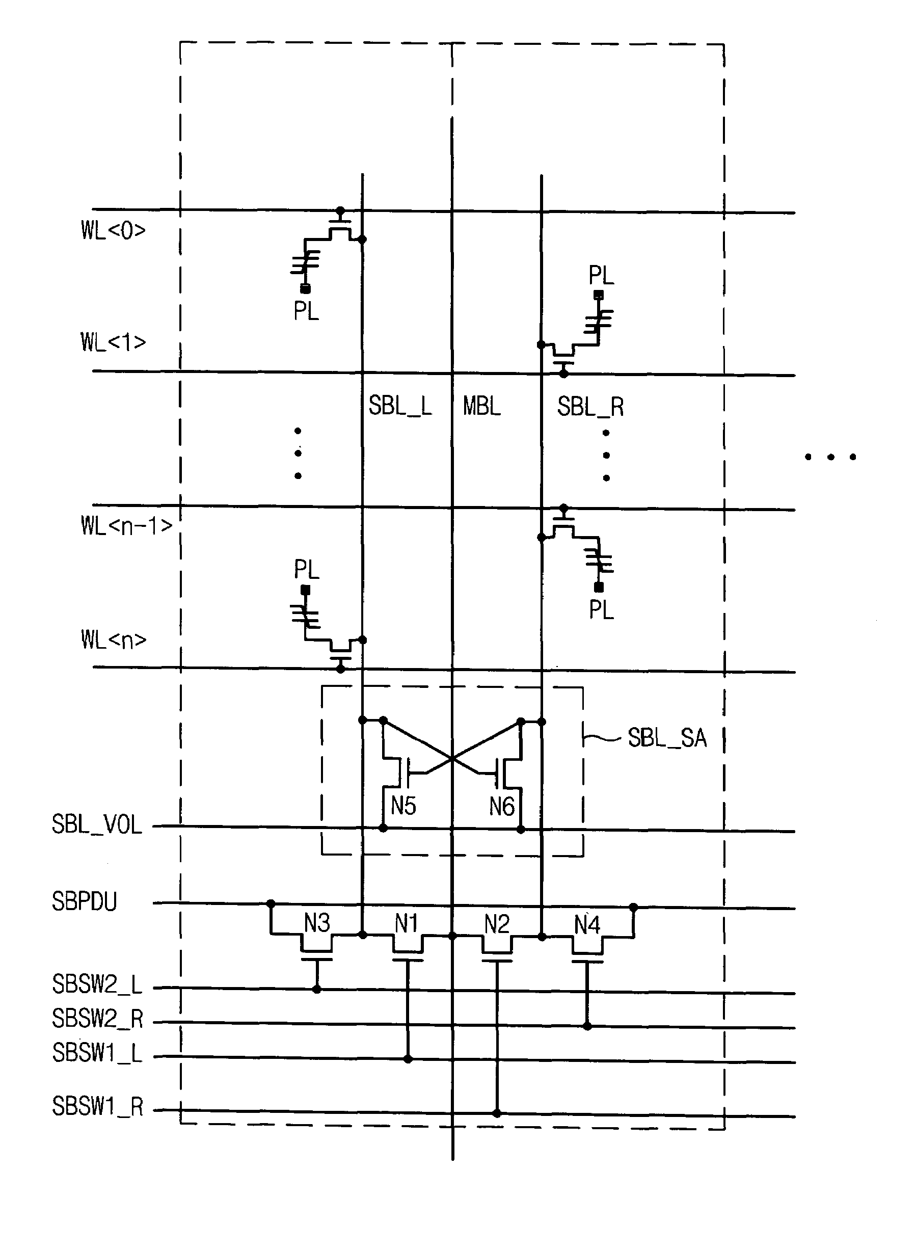
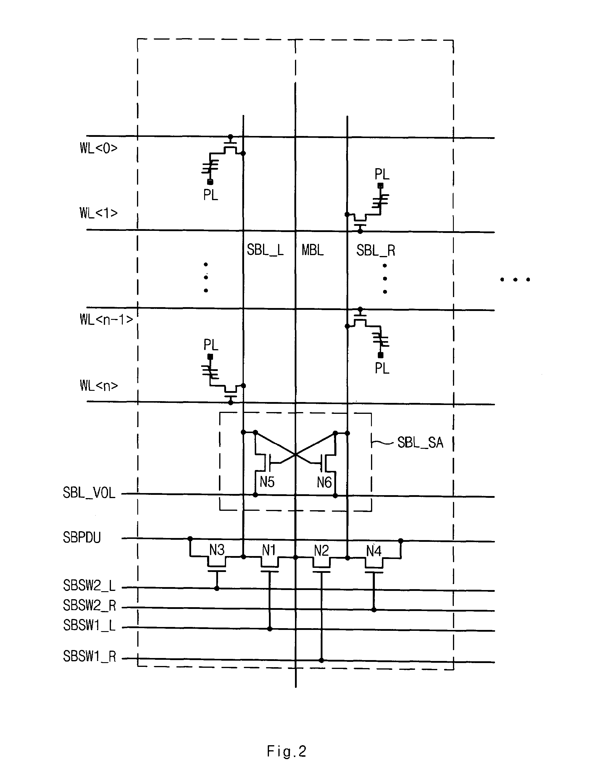
The present invention discloses a non-volatile ferroelectric cell array block having a hierarchy transfer sensing architecture. The cell array block of the invention includes a plurality of sub cell arrays, each with a hierarchy bit line architecture; a plurality of sub bit line sense amplifiers for amplifying a voltage of a sub bit line; main bit line sense amplifier for amplifying a voltage of a main bit line; and a word / plate driver for selectively activating the word line and the plate line in the sub cell array. The cell array block of the invention can be advantageously used for performing more stable read and write operations on a data even with a small sized cell, by having a sub bit line capacitance independent of the main bit line.

Description

BACKGROUND OF THE INVENTION[0001]1. Field of the Invention[0002]The present invention relates to a non-volatile ferroelectric cell array block having a hierarchy bit-line architecture, and more particularly, to non-volatile ferroelectric cell array block having a hierarchy transfer sensing architecture, in which during a cell data sensing operation, the capacitance of a respective sub bit-line is independent of the capacitance of a main bit-line so that cell sensing capacitance is limited to the capacitance of the sub bit-line.[0003]2. Description of the Background Art[0004]The ferroelectric memory, i.e., a FeRAM (Ferroelectric Random Access Memory), is paid a lot of attention as a next generation memory because it has a data processing speed similar to that of a DRAM (Dynamic Random Access Memory) and also is capable of preserving stored data even when the power is off.[0005]FeRAM is a memory device having a structure very similar to DRAM, and uses capacitors made of a ferroelectri...

Claims


Application Information

Patent Timeline
Patent Type & Authority Patents(United States)
IPC IPC(8): G11C11/22G11C5/06
CPCG11C11/22G11C29/028G11C2029/5004
Inventor KANG, HEE BOK
Owner SK HYNIX INC
Learn More