Power blower having a debris-catching cover

a technology of blower and debris, which is applied in the direction of machines/engines, liquid fuel engines, and turf growing, etc., can solve the problems of reducing the air intake efficiency of the blower, prime mover, and debris such as fallen leaves, so as to increase the area (overall ventilation area), slow down the air intake flow, and easy to remov

Active Publication Date: 2006-06-06
KIORITZ
View PDF12 Cites 28 Cited by
  • Summary
  • Abstract
  • Description
  • Claims
  • Application Information

AI Technical Summary

Benefits of technology

[0008]Accordingly, it is an object of the present invention to provide a power blower that inhibits the occurrence of problems such as the reduction of intake efficiency of the blower, and that facilitates the removal operation for debris sticking to the debris-catching cover.
[0009]The power blower according to an embodiment of the present invention includes a frame, and a blower mounted on the frame. An air intake port of the blower faces the frame. There is provided an air intake space between the blower and the frame. A debris-catching cover is constructed between the frame side and the blower side in a state in which it is mounted on both the frame and blower sides. The debris-catching cover inhibits debris from being sucked from the air intake space into the air intake port.
[0010]According to the present invention, because the debris-catching cover is constructed between the frame side and the blower side, the debris-catching cover can have a large overall ventilation area by, for example, increasing the number of ventilation holes. This prevents the debris-catching cover from hindering an intake action of the blower. This also allows the intake air flow passing through the debris-catching cover to be slowed down, thereby inhibiting debris such as fallen leaves from sticking to the debris-catching cover. Thus, the occurrence of the problem of reduction of intake efficiency of the blower due to the sticking of debris is prevented. In this case, even if debris stick to the debris-catching cover, they could be easily removed.

Problems solved by technology

However, debris such as fallen leaves may stick to the debris-catching cover due to the intake airflow of the blower.
Leaving this state as it is, may cause a problem in that the air intake efficiency of the blower is reduced, or that a prime mover for driving the blower seizes up due to an insufficient supply of cooling air.
Therefore, an operator may need to remove the debris sticking to the debris-catching cover by hand.
This may be a complicated and time-consuming effort, resulting in a reduced working efficiency.

Method used


Image

  • Power blower having a debris-catching cover
  • Power blower having a debris-catching cover
  • Power blower having a debris-catching cover

Examples


Embodiment Construction

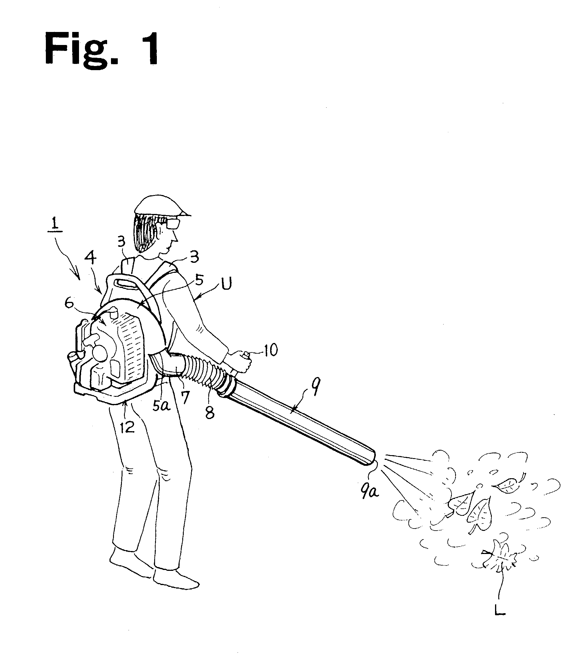
[0025]FIG. 1 shows a backpack-type power blower 1 as a power blower according to an embodiment of the present invention. The backpack-type power blower 1 is suitable for blowing fallen leaves L or the like.

[0026]Referring to FIG. 1, the backpack-type power blower 1 includes, a portable-type frame, and more specifically, a backpack frame 4 having a pair of left and right shoulder belts 3. The backpack frame 4 is equipped with a blower 5 of, for example, a centrifugal type, and an internal-combustion engine 6, such as an air-cooled two-cycle gasoline engine, as a prime mover for driving the blower 5. An air-blowing pipe 9 is connected to an air-discharging port 5a of the blower 5 via an elbow pipe 7 and a bellows hose 8.

[0027]An operator U puts the backpack frame 4 on his or her back with the pair of left and right shoulder belts 3, holds a grip 10 attached to the proximal end of the air-blowing pipe 9, and can efficiently perform a blowing operation to move debris such as fallen leav...


PUM

PropertyMeasurementUnit
diameteraaaaaaaaaa
sizeaaaaaaaaaa
shapeaaaaaaaaaa

Abstract

A power blower includes a frame, and a blower mounted on the frame. An air intake port of the blower faces the frame. There is provided an air intake space between the blower and the frame. A debris-catching cover is constructed between the frame side and the blower side in a state in which it is mounted on both the frame and blower sides. The debris-catching cover inhibits debris from being sucked from the air intake space into the air intake port.

Description

[0001]This application claims the benefit of Japanese Patent Application No. 2002-61577, filed Mar. 7, 2002, which is herein incorporated by reference in its entirety.BACKGROUND[0002]1. Field of the Invention[0003]The present invention relates to a power blower having a debris-catching cover. More particularly, it relates to a power blower having a frame and a blower, the blower being spaced apart from the frame by an air intake space and having an air intake port facing the frame.[0004]2. Background of the Invention[0005]As an example of a power blower, a backpack-type power blower is known, which is suitable for blowing fallen leaves, lawn clippings, or the like. This power blower has a frame, and a blower mounted on the frame. An air intake port of the blower faces the frame. There is provided an air intake space between the blower and the frame.[0006]Some conventional power blowers have, on a blower case, a debris-catching ventilation cover that directly covers the air intake po...

Claims


Application Information

Patent Timeline
Patent Type & Authority Patents(United States)
IPC IPC(8): A47L5/00A47L5/14E01H1/08F02B63/02F02B75/02F04D29/44F04D29/70
CPCA47L5/14E01H1/0809A01G1/125F02B63/02F02B2075/025F05C2225/02A01G20/47
Inventor IIDA, GIICHIKAMOSHITA, TADASHI
Owner KIORITZ
Why Eureka
Try Eureka