High efficiency cooling system and heat absorbing unit

a high-efficiency cooling and heat-absorbing technology, applied in domestic cooling apparatus, semiconductor/solid-state device details, capacitors with temperature varied dielectrics, etc., can solve the problem of simple liquid coolant use and lower cooling efficiency, and achieve the effect of facilitating piping structure and improving cooling efficiency

Inactive Publication Date: 2006-06-06
FUJITSU LTD
View PDF19 Cites 43 Cited by
  • Summary
  • Abstract
  • Description
  • Claims
  • Application Information

AI Technical Summary

Benefits of technology

[0008]It is accordingly an object of the present invention to provide a cooling...

Problems solved by technology

However, the latter cooling system is only allowed to utilize a heat transfer to a liquid coolant to cool a target heat generating object.
A simple employmen...

Method used


Image

  • High efficiency cooling system and heat absorbing unit
  • High efficiency cooling system and heat absorbing unit
  • High efficiency cooling system and heat absorbing unit

Examples


first embodiment

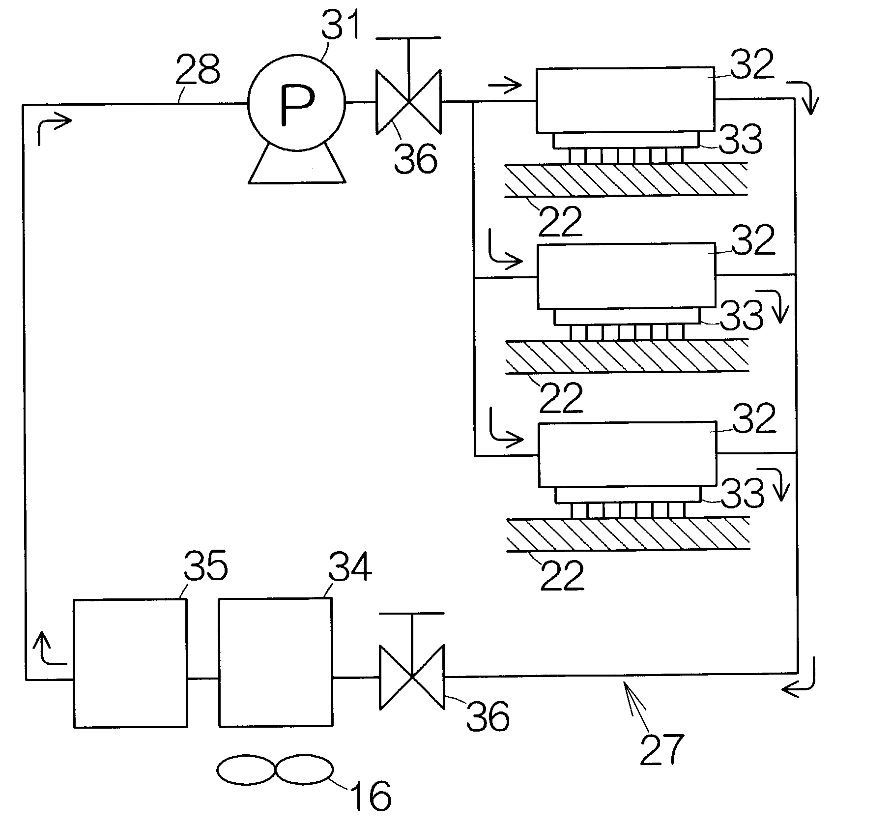
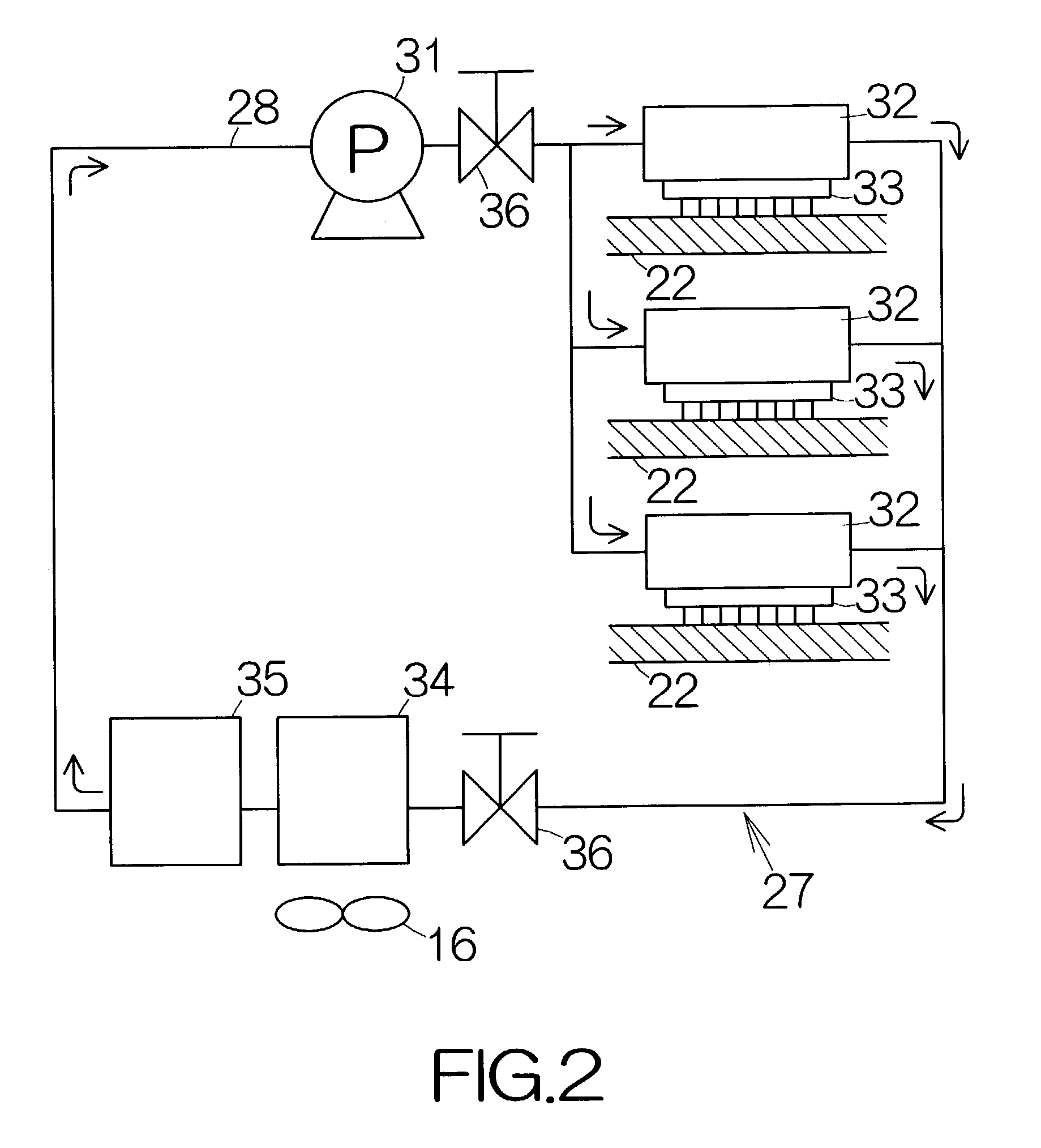
[0047]Heat absorbing units 32 are incorporated in the circulation channel 28 downstream of the pump 31. The heat absorbing units 32 individually cover over the corresponding CPUs 33 on the motherboards 22. The liquid coolant discharged out of the pump 31 is allowed to get evaporated in the heat absorbing units 32. The evaporation of the coolant serves to cool the CPUs 33. The vaporized coolant, namely, the gaseous coolant is discharged out of the heat absorbing units 32. The liquid coolant may be mixed in the gaseous coolant at the outlets of the heat absorbing units 32. The structure of the heat absorbing unit 32 will be described later in detail.

[0048]A condensation unit or heat exchanger 34 and a receiver tank 35 are in this sequence incorporated in the circulation channel 28 downstream of the heat absorbing units 32. The heat exchanger 34 serves to absorb heat from the gaseous coolant discharged from the heat absorbing units 32. The gaseous coolant is allowed to get condensed i...

second embodiment

[0057]FIG. 7 illustrates a heat absorbing unit 61 in detail. The heat absorbing unit 61 includes a housing 65 defining a closed space 64 between a top plate 62 and a bottom plate 63 in the same manner as described above. The bottom plate 63 is allowed to contact a target heat generating object, namely, the CPU 33. A first partition wall or intermediate plate 66 is disposed in the housing 65 between the top and bottom plates 62, 63. The periphery of the intermediate plate 66 is connected to the inner wall surface of the housing 65. An evaporation chamber 67 is thus defined between the intermediate plate 66 and the bottom plate 63. A heat transfer surface of the evaporation chamber 67 is defined on the upper surface of the bottom plate 63 contacting the CPU 33 in the same manner as described above. The bottom plate 63 of the housing 65 may be made of a high heat conductive material such as aluminum, for example.

[0058]A second partition wall or surrounding wall 68 is disposed between ...


PUM


Abstract

The cooling system allows the liquid coolant discharged from the pump to flow into the evaporation chamber. The liquid coolant passes through the atomizer. Minute droplets of the atomized coolant is discharged from the atomizer into the evaporation chamber. The minute droplets serve to form a uniform thin liquid film over the surface of the fin. Heat conducting from a target heat generating object to the fin promotes the evaporation of the liquid coolant over the surface of the fin, for example. The coolant absorbs a large amount of heat from the fin based on the evaporation. The target heat generating object can thus efficiently be cooled.

Description

[0001]This application is a continuation of international application PCT / JP00 / 08571, filed on Dec. 4, 2000.BACKGROUND OF THE INVENTION[0002]1. Field of the Invention[0003]The present invention relates to a cooling system designed to cool a heat generating object such as a high density device, for example. In particular, the invention relates to a cooling system including: a circulation channel; a pump disposed in the circulation channel so as to force a coolant to circulate through the circulation channel; and a heat absorbing unit disposed in the circulation channel downstream of the pump so as to receive the coolant of the liquid state from the pump.[0004]2. Description of the Prior Art[0005]A refrigeration system may represent a cooling system employing a circulation channel of the closed loop. The refrigeration system employs a so-called compressor for forcing a coolant to circulate through the circulation channel. The compressor is in general capable of discharging the coolant...

Claims


Application Information

Patent Timeline
IPC IPC(8): F28F7/00H01L23/427
CPCH01L23/427F28D2015/0225H01L2224/16
Inventor NORI, HITOSHIWEI, JIE
Owner FUJITSU LTD
Why Eureka
Try Eureka