Electromagnetic valve control device and method

a control device and electronic technology, applied in the direction of braking system, magnetic body, water supply installation, etc., can solve the problem of loud impact noise and achieve the effect of reducing the noise generated

Inactive Publication Date: 2006-06-06
TOYOTA JIDOSHA KK
View PDF17 Cites 17 Cited by
  • Summary
  • Abstract
  • Description
  • Claims
  • Application Information

AI Technical Summary

Benefits of technology

[0006]The object of the invention is to reduce the noise generated by operation of the electromagnetic valve during an abnormality chec...

Problems solved by technology

When the valve hits the valve seat at this time, a loud...

Method used


Image

  • Electromagnetic valve control device and method
  • Electromagnetic valve control device and method
  • Electromagnetic valve control device and method

Examples


Embodiment Construction

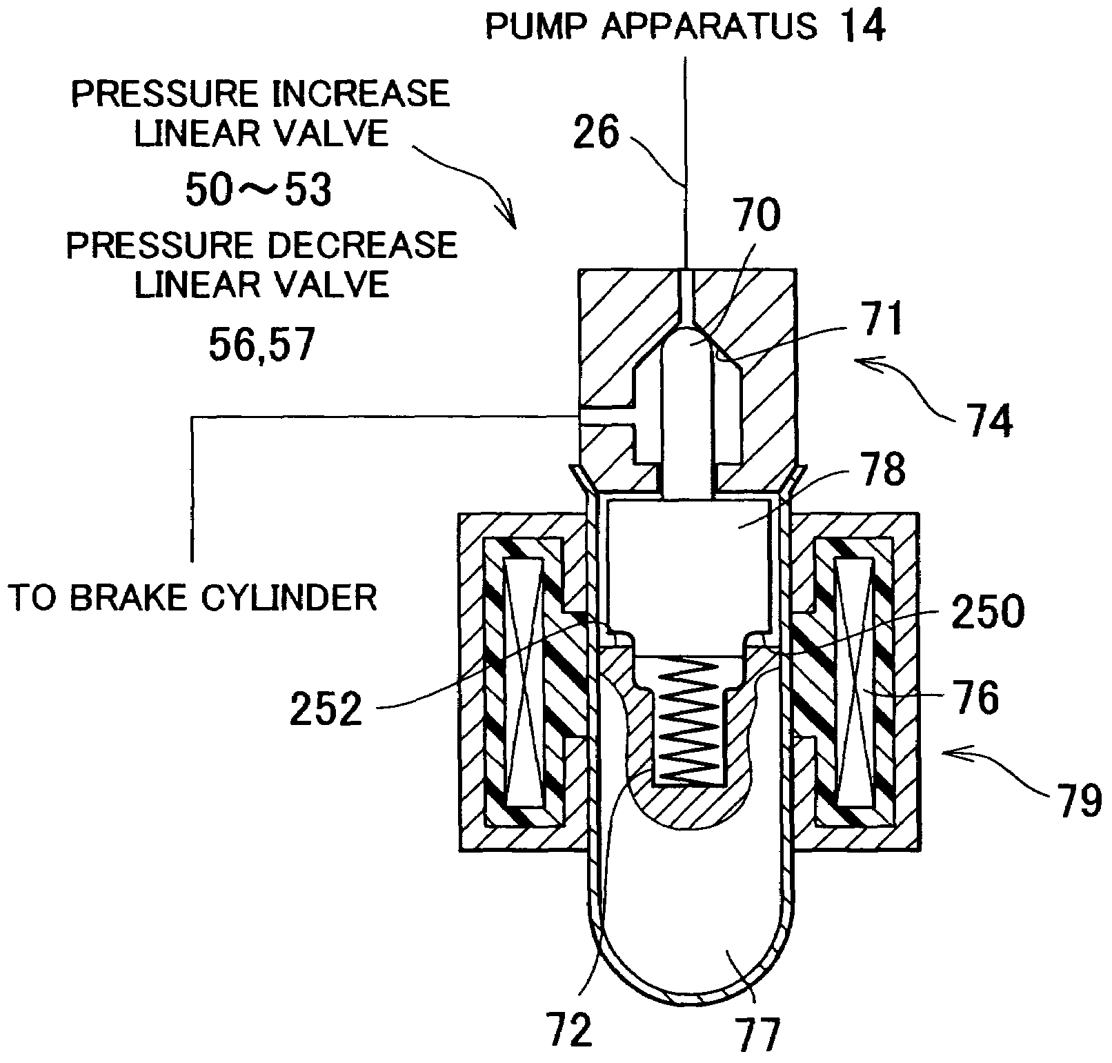
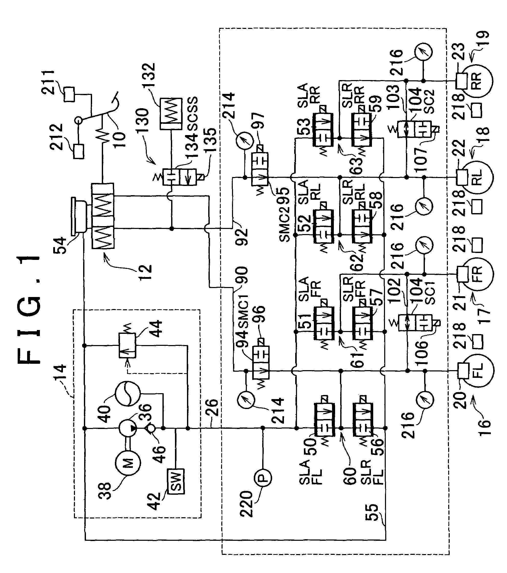
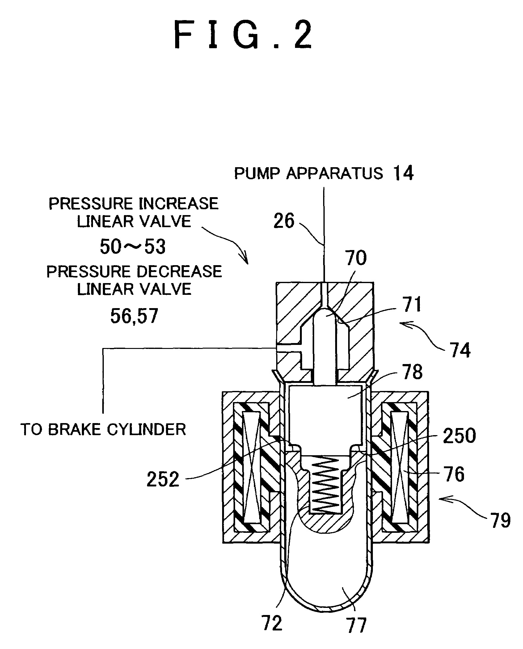
[0055]A case in which an electromagnetic valve control device according to one exemplary embodiment of the invention is applied as a brake fluid pressure control device which controls a fluid pressure of a brake cylinder will be described. The brake fluid pressure control device controls the fluid pressure of brake cylinders of a brake system shown in FIG. 1.

[0056]The brake system shown in the drawing includes a brake pedal 10 as a brake operating member, a master cylinder 12 that includes two pressure chambers, a pump apparatus 14 as a power fluid pressure generating device that is operated with power, and brakes 16 to 19 provided for left and right front and rear wheels, respectively. The brakes 16 and 17 are right and left front wheel brakes, and the brakes 18 and 19 are left and right rear wheel brakes. Brake cylinders 20 to 23 for the four brakes 16 to 19 are connected to the pump apparatus 14 by a brake line 26 such that brake fluid from the pump apparatus 14 is supplied to th...


PUM


Abstract

A normally closed electromagnetic valve is closed again after temporarily being opened during an abnormality check of the valve. When the valve is opened, electricity is supplied so that a plunger is moved by a coil but a back face of the plunger does not abut against a receiving face of a fixed portion. Because the plunger does not strike the fixed portion, no impact noise is generated. Also, when the valve is closed, the electricity is not instantly dropped to zero, but is gradually reduced. As a result, impact noise when the valve strikes the valve seat is able to be reduced.

Description

INCORPORATION BY REFERENCE[0001]The disclosure of Japanese Patent Application No. 2002-245044 filed on Aug. 26, 2002, including the specification, drawings and abstract is incorporated herein by reference in its entirety.BACKGROUND OF THE INVENTION[0002]1. Field of the Invention[0003]The invention relates to an electromagnetic valve control device that controls an electromagnetic valve, and more particularly to an electromagnetic valve control device that controls a current supplied to the electromagnetic valve when checking for an abnormality.[0004]2. Description of the Related Art[0005]JPA 10-24826 discloses an electromagnetic valve control device which includes i) an electromagnetic valve that has a) a seating valve having a valve seat and a valve that can be placed against and separated from the valve seat, and b) an electromagnetic driving device which includes a coil retained in a body and a plunger that moves relative to the body when electricity is supplied to the coil, and ...

Claims


Application Information

Patent Timeline
IPC IPC(8): F16K37/00F16K31/02B60T8/88B60T8/36B60T8/40F16K31/06H01F7/18
CPCB60T8/36B60T8/367B60T8/4081F16K31/0675F16K31/0689B60T8/90H01F7/1844Y10T137/0318Y10T137/8175Y10T137/8225
Inventor SUZUKI, MASAKUNI
Owner TOYOTA JIDOSHA KK
Why Eureka
Try Eureka