Automatic row crop implement positioner

a technology of crop implements and positioners, which is applied in the direction of agricultural machines, applications, instruments, etc., can solve the problems of damage to crops, damage to crops, and damage to plants, and achieve the effect of high degree of accuracy

Active Publication Date: 2006-06-06
KIEL CHRISTIAN
View PDF1 Cites 11 Cited by
  • Summary
  • Abstract
  • Description
  • Claims
  • Application Information

AI Technical Summary

Benefits of technology

[0007]It is the primary objective of the present invention to provide a method by which the position of a tractor drawn harvester or cultivator type farm implement, relative to the individual rows of a row crop such as sugar beets, can be constantly monitored and adjusted to ensure that the towed harvester is maintained in the proper position enabling it to perform its designed function at the highest degree of accuracy possible.
[0008]It is an additional objective of the present invention to provide such a method of positioning a towed farm implement that will automatically make the necessary adjustments in its position relative to the row crop without the need for any major corrective inputs from the operator of the towing tractor while working the field.
[0009]It is a further objective of the present invention to provide such a method of positioning a towed farm implement which is equipped with a pair of sensing feet that are pivotally mounted in a manner which allows for the greatest degree of pivotal flexibility providing them with a means by which they can be employed to monitor the position of the farm implement to the highest degree of accuracy possible which will translate to it operating at its greatest possible potential and result in higher crop yields.
[0014]Additionally, the vertical plane adjustments are accomplished through a detected variance in the vertical orientation of the sensing feet which is transferred to the vertical sensing valve through a connecting linkage. These vertical variances are then transferred to the vertical adjustment cylinder through the hydraulic pressure and return lines. The vertical adjustment cylinder then adjusts the vertical orientation of the harvester or cultivator through its expansion or contraction which raises or lowers the diggers attached to the implement frame in relation to the surface of the field. The use of this system ensures that the diggers are constantly maintained in the proper orientation with respect to the field enabling the harvester or cultivator to operate at its maximum potential at all times.

Problems solved by technology

This requirement creates difficulties as it is very hard for the operator of the towing vehicle to maintain the proper orientation as he travels up and down the row crop both because the rows are never completely straight and the towing vehicle may tend to wander relative to a straight line due to surface conditions or problems in the directional control apparatus of the towing vehicle.
These horizontal variances often lead to damage to the crop as the diggers can be far enough off line to result in a destroyed or entirely missed plants.
Additionally, variances in the level or composition of the field surface can create problems in the vertical orientation of the towed implement causing the attached diggers to dig too deeply or to skip over entire sections of the row crop.
Again, this misalignment in the vertical orientation can result in damage to the crop and implement or to a situation where sections of the row crop are left uncultivated or unharvested in the field, either of which are undesirable to the farmer.
While the described apparatus accomplished its stated goals, a problem with its design results in deficits in its sensitivity and responsiveness that limit its overall effectiveness in the function for which it was designed.
This problem is a result of the manner employed to pivotally attach the sensing shoes to the remaining portion of the apparatus in that they are not freely pivotal in all axises and therefore limited in their range of motion.
This method of construction results in an apparatus that is less sensitive and responsive than is desirable and therefore, of limited value to the row crop farmer.

Method used


Image

  • Automatic row crop implement positioner
  • Automatic row crop implement positioner
  • Automatic row crop implement positioner

Examples


Embodiment Construction

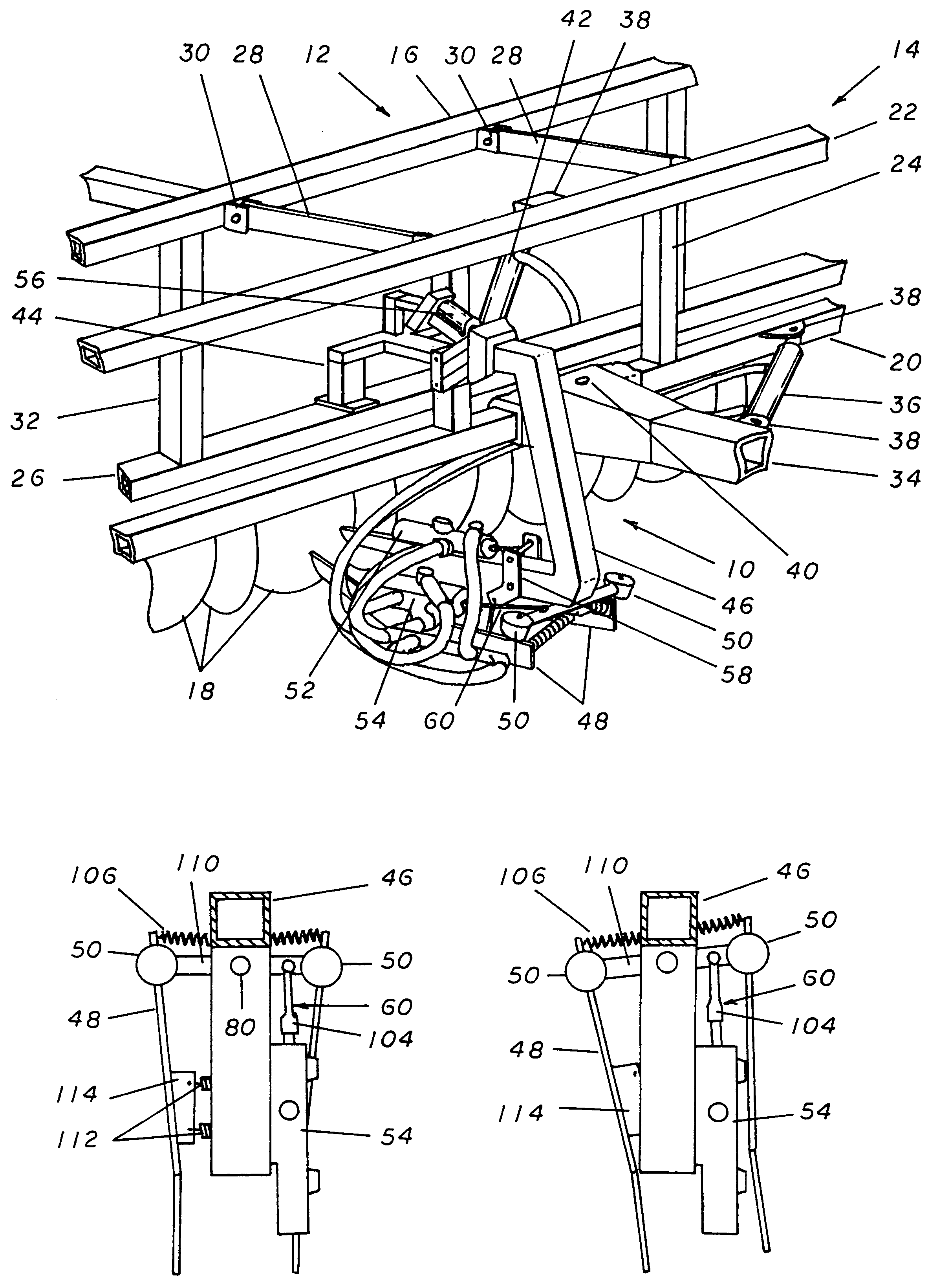
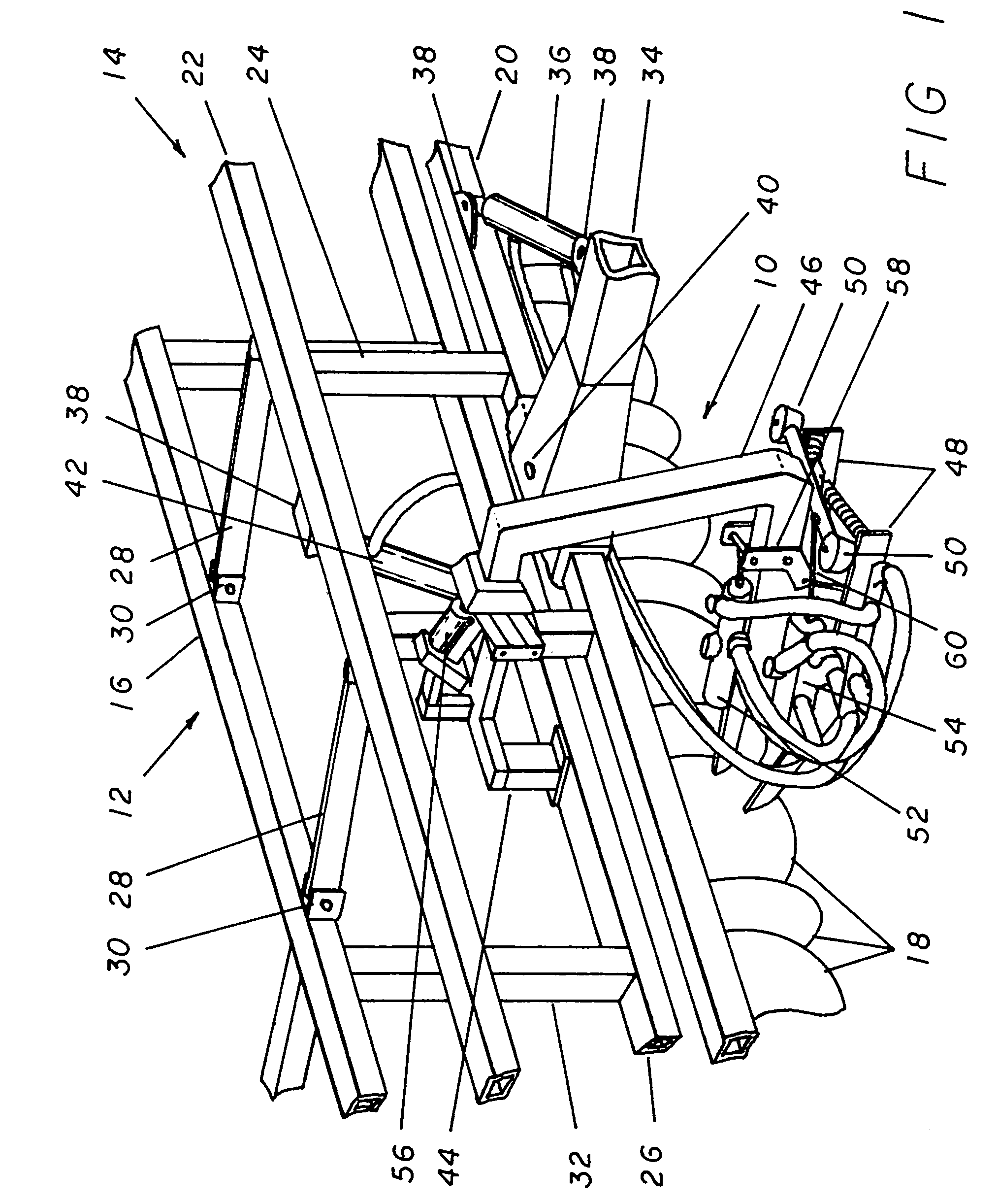
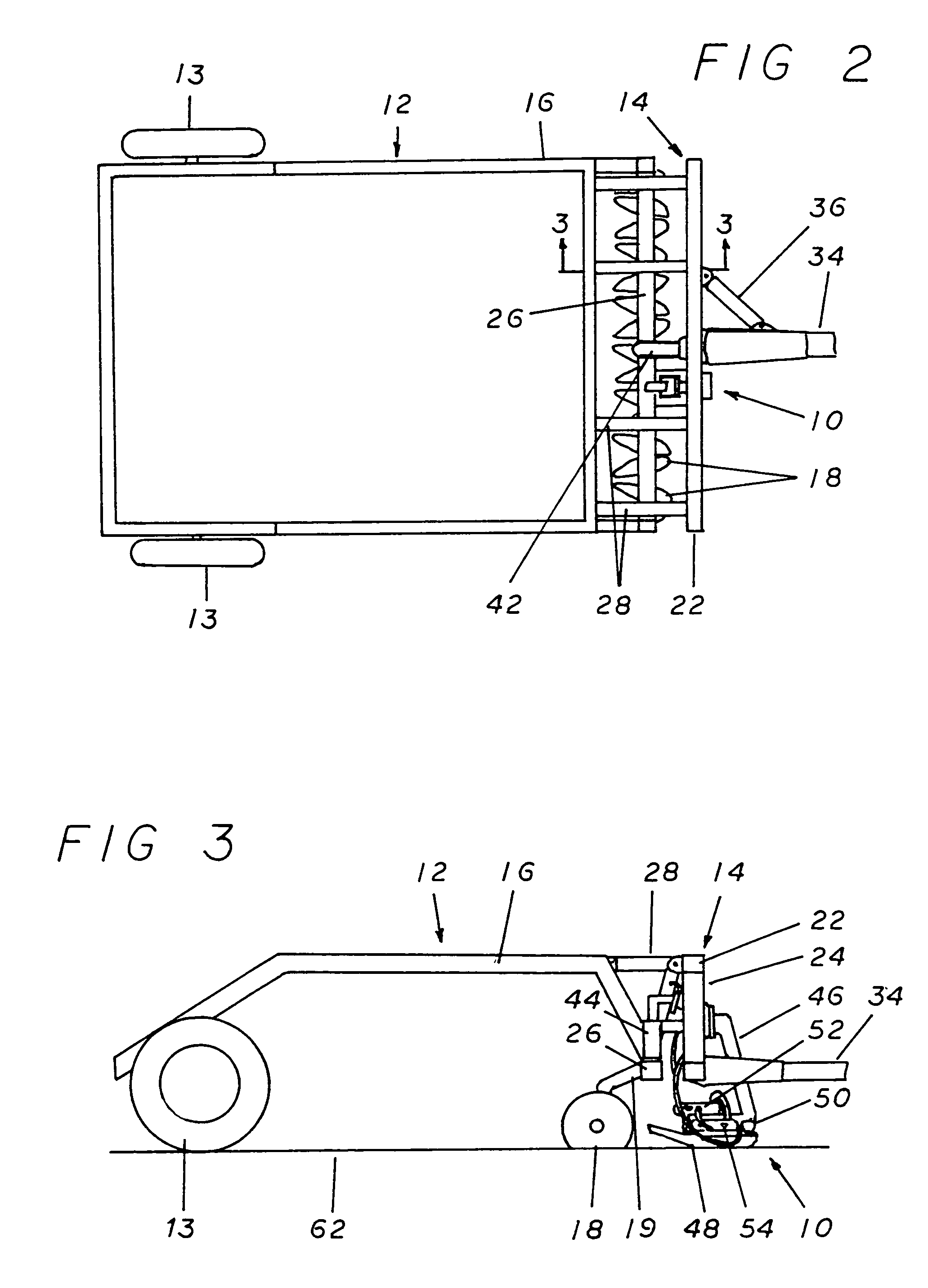
[0027]Referring now to the drawings, and more specifically to FIGS. 1, 2, and 3, the positioning control apparatus 10 is a device that connects to towed farm implements such as a harvester 12 or other similar devices and is employed to keep the harvester 12 in the proper alignment when a farmer is working in a row crop. For the purpose of simplicity, the positioning control apparatus 10 herein illustrated is represented as used in conjunction with a harvester 12 but it must be noted that it would work equally well with any towed implement commonly used in the working of row crop fields. Additionally, the illustrated harvester 12 is intended to represent a generalized form of harvesters and is not intended as a depiction of a specific type of implement.

[0028]The harvester 12 is generally made up of two connected frames. The most forward of these is the primary frame 14 which is the portion of the harvester 12 employed to attach it to the towing vehicle and from which the second porti...


PUM


Abstract

A row following apparatus that attaches to the forward portion of the frame of a tractor towed harvester or cultivator which operates to monitor and adjust the position of the harverster. The row following apparatus uses a pair of pivotally attached sensing feet for following the crop rows. These sensing feet are attached to the frame of the present invention by a pair of automotive style ball joints. The use of the ball joints allows the pivotal movement of the sensing feet in a 360 degree manor that is unattainable with other methods of attachment.

Description

BACKGROUND OF THE INVENTION[0001]The present invention relates to an improvement in the methods used to control the position of farm implements, such as harvesters, relative to the location of the individual plants of a row crop within which the implement is being employed. More specifically, to a method of automatically adjusting the relative position of such implements in regards to the row crop without requiring the operator to make constant adjustments to the attitude of the towing vehicle.[0002]The production of row crops such as sugar beets requires the use of specialized farm implements such as cultivators and harvesters that are drawn through the field during cultivating and harvesting operations. These procedures require that the farm implements be properly oriented at all times relative to the individual plants and their related rows comprising the row crop. This requirement creates difficulties as it is very hard for the operator of the towing vehicle to maintain the prop...

Claims


Application Information

Patent Timeline
Patent Type & Authority Patents(United States)
IPC IPC(8): A01B63/111G06F19/00G06F7/70G06G7/00G06G7/76
CPCA01B39/22A01D33/14A01D33/00
Inventor KIEL, CHRISTIAN
Owner KIEL CHRISTIAN
Why Eureka
Try Eureka