Separable laminated container and associated technology

a technology of laminated containers and containers, which is applied in the direction of pliable tubular containers, instruments, single-unit apparatuses, etc., can solve the problems of difficult fusion of outer layers, difficult to form air suction holes, and restrict the selection of resins used for inner layers and outer layers

Inactive Publication Date: 2006-06-06
YOSHINO KOGYOSHO CO LTD
View PDF30 Cites 5 Cited by
  • Summary
  • Abstract
  • Description
  • Claims
  • Application Information

AI Technical Summary

Benefits of technology

[0090]In the pre-separation device with the eleventh feature of the present invention, the first air supply member may comprise a nozzle inserted into the air suction hole of the separable laminated container, wherein the nozzle is opened at the front end and a side thereof so that the air supplied between the inner layer and the outer layer is discharged through the nozzle when air is blown into the separable laminated container through the second air supply member. As structured above, the air introduced between the inner layer and the outer layer can be completely discharged with the second air supply member is mounted on the separable laminated container, with the result that the entire surface of the separated inner layer can be brought in contact with the inner surface of the outer layer as the original state.

Problems solved by technology

However, the method of forming the air suction hole as mentioned above has following problems.
In case of a little difference between the melting points of the inner layer and the outer layer, it is quite difficult to fuse the outer layer only.
Therefore, a predetermined difference in temperature between the melting points of the inner layer and the outer layer is required, thereby restricting the selection of resins used for the inner layer and the outer layer.
Since the air suction hole is formed by fusing the resin of the outer layer by the fusion means, it is difficult to sharply form the air suction hole into a predetermined configuration.
Therefore, there is a problem that the separation can not be completed overall when the control of blowing is mistook.
Further, a control unit is necessary for controlling the amount of air, thereby complicating the device.
This causes a cracking of the pinch-off portion and a slit between the layers due to a separation, thereby causing a sealing defect.
There is a problem that the container entraps moisture between the inner layer and outer layer from the sealing defect when the container is used in a damp area.
Since, once separated from the outer layer, the inner layer is returned in such a manner as to cling to the inner surface of the outer layer in the conventional pre-separation, the level to which the pre-separation is finished does not appear externally so that it is difficult to inspect the level.

Method used


Image

  • Separable laminated container and associated technology
  • Separable laminated container and associated technology
  • Separable laminated container and associated technology

Examples


first embodiment

[First Embodiment]

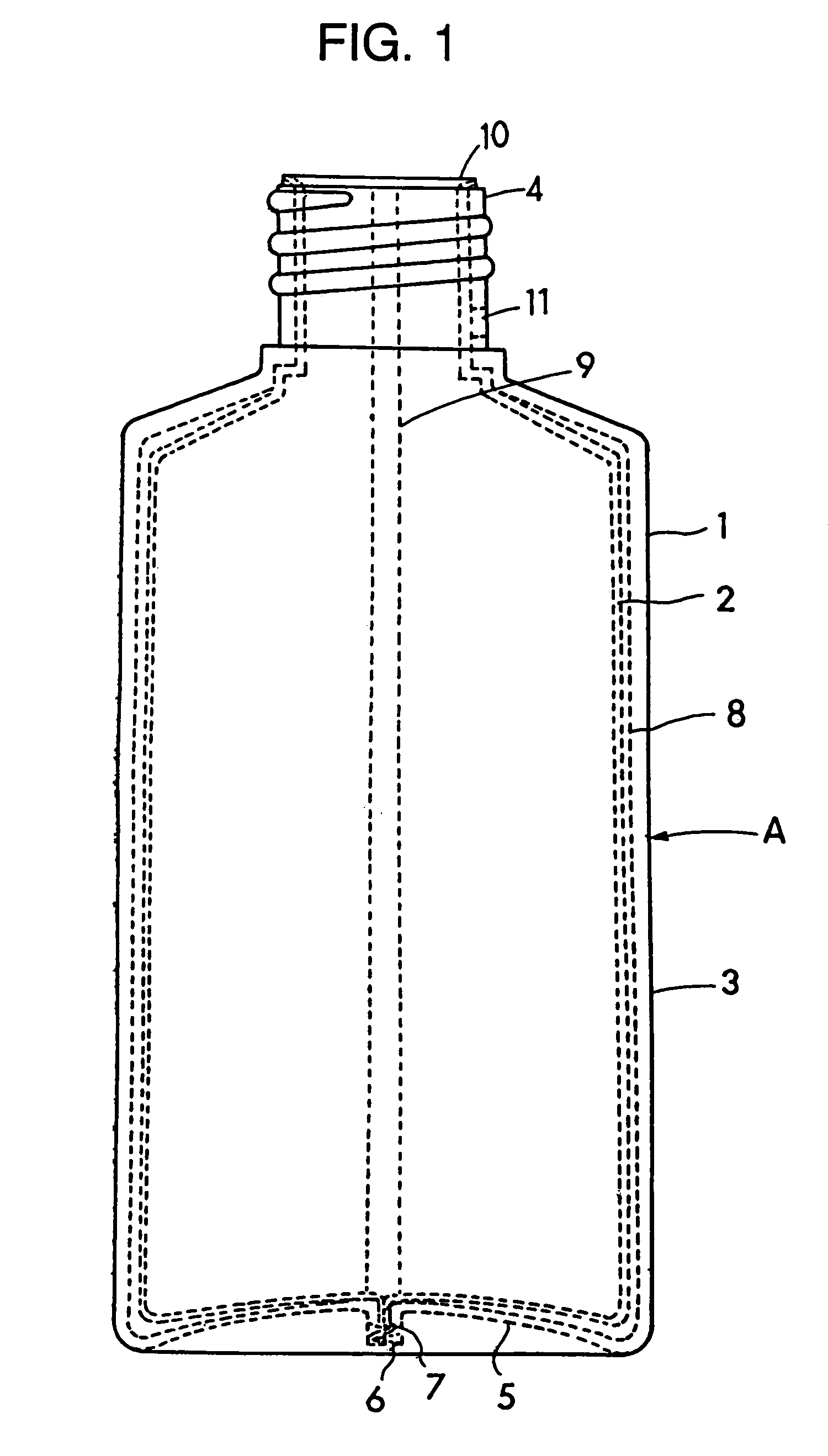
[0129]FIG. 1 is a front view of a separable laminated container A-according to a first embodiment. The separable laminated container A is made up of an outer layer 1 and an inner layer 2, is formed by blow molding, and comprises a drum portion 3, a neck 4, and a bottom 5.

[0130]The outer layer 1 is made of high-density polyethylene to keep the profile of the container, and the inner layer 2 is an inner bag made of nylon which is separable from the outer layer and deformable. There is a separated area 8 formed between the outer layer 1 and the inner layer 2 and a bonded area 9 where the outer layer 1 and the inner layer 2 are partly bonded in the longitudinal direction.

[0131]The bottom 5 of the container A is provided with a projection 6 which is formed by pinch-offs of a mold during the molding. The projection 6 is provided with a plurality of sunk portions 7 which are arranged zigzag and each sunk in the opposite bonded layer.

[0132]The projection 6 allows the inner...

second embodiment

[Second Embodiment]

[0162]FIG. 3 is a perspective view of a separable laminated container A according to a second embodiment, FIG. 4 is a plan view of the same, and the FIG. 5 is a cross-sectional view of a drum portion thereof.

[0163]The container A comprises a drum portion 102 having an elliptical section, a shoulder 103 continuously connected to the upper part of the drum portion 102, and a cylindrical neck 104 extending upward from the center of the shoulder 103. The container A is made up of an outer layer 111 and an inner layer 112 overall from the neck 104 to a bottom 105 of the drum portion 102. The outer layer 111 and the inner layer 112 are bonded each other at a strip of bonded area 113, while the outer layer 111 and the inner layer 112 are just in contact with each other besides the bonded area 113 in such a manner as to be separable from each other. FIG. 5 shows a state before the inner layer 112 is separated from the outer layer 111.

[0164]The bonded area 113 linearly ext...

third embodiment

[Third Embodiment]

[0181]FIG. 6 is a front view of a separable laminated container A according to a third embodiment wherein parts being broken away and FIG. 7 is a longitudinal sectional view of the same, as seen from the side.

[0182]The separable laminated container A is made up of an outer layer 201 and an inner layer 202 and comprises a drum portion 203, a neck 204, and a bottom 205.

[0183]The outer layer 201 is made of high-density polyethylene to keep the profile of the container, and the inner layer 202 is an inner bag made of nylon which is separable from the outer layer and deformable. The outer layer 201 and the inner layer 202 of the container A are made by blow molding of a laminated parison which is formed by co-extrusion.

[0184]In this embodiment, the nylon used in the inner layer 202 is copolymer of nylon 6 having flexural modules of 650 kg / cm2, providing excellent flexibility.

[0185]Besides the nylon 6, any other nylon or any other synthetic resin material may be employed...


PUM

PropertyMeasurementUnit
volumeaaaaaaaaaa
volumeaaaaaaaaaa
shrinkageaaaaaaaaaa

Abstract

A separable laminated container (A) of the present invention comprises an outer layer (1) made of synthetic resin and having an air suction hole (10) and an inner layer (2) made of synthetic resin and separably laminated on the inside of the outer layer, the inner layer having a portion previously separated from the outer layer just around the air suction hole. The air suction hole can be formed by driving a punch into the outer layer at a neck (4) of the separable laminated container from the outside, and punching just the outer layer leaving the inner layer behind. The portion of the inner layer previously separated from the outer layer may be left in the inwardly extended state. The inner layer is preferably made of synthetic resin having flextural modules of less than 10,000 kg/cm2.

Description

[0001]This is a Division of application Ser. No. 09 / 866,766 filed May 30, 2001 and issued as U.S. Pat. No. 6,691,494 B2 on Feb. 17, 2004, which is in turn a Division of application Ser. No. 08 / 737,020 filed Nov. 1, 1996 and issued as U.S. Pat. No. 6,266,943 B1 on Jul. 31, 2001, which in turn claims priority under 35 U.S.C. §365 of Japanese Patent Application Nos. Hei 07-088558 filed Mar. 10, 1995, Hei 07-140105 filed May 16, 1995, 7-177936 filed Jun. 22, 1995, Hei 07-232038 filed Aug. 18, 1995, and Hei 07-235463 filed Sep. 13, 1995 in Japan for National Stage of PCT / JP96 / 00543 on Mar. 6, 1996. The entire disclosures of the prior applications, together with the foreign priority applications, are hereby incorporated by reference in their entirety.BACKGROUND[0002]1. Technical Field[0003]The present invention relates to a separable laminated container, of which an inner layer is separated from an outer layer and shrinks according to the decrease of the liquid content, and the related ar...

Claims


Application Information

Patent Timeline
Patent Type & Authority Patents(United States)
IPC IPC(8): B65D35/28B05B11/00B29C49/04B29C49/22B65D1/02B65D83/00G01F11/02
CPCB05B11/0043B05B11/3047B29C49/22B65D1/0215B65D83/0055G01F11/028B29C49/04B29C2793/0045B29C2793/0054Y10S83/914B29L2009/00B29L2009/001B29L2031/7158B29C2793/009Y10T83/9416B05B11/026B05B11/1047B29C2949/3094B65D1/02
Inventor NOMOTO, TSUGIOGOTO, TAKAYUKIYONEYAMA, MASASHISHIBANO, YOSHIOAKIYAMA, YOSHIO
Owner YOSHINO KOGYOSHO CO LTD
Why Eureka
Try Eureka