Liquid jet recording head and process for production thereof

a liquid jet and recording head technology, applied in printing and other directions, can solve the problems of invariable flow resistance, limited working precision in cutting or etching glass plates or metal plates, and disadvantageous variation of recording characteristics of produced liquid jet recording heads, etc., to achieve high mechanical strength, low water absorption, and high adhesiveness to a base plate

Inactive Publication Date: 2006-06-06
CANON KK
View PDF22 Cites 22 Cited by
  • Summary
  • Abstract
  • Description
  • Claims
  • Application Information

AI Technical Summary

Benefits of technology

[0025]An object of the present invention is to provide a liquid jet recording head composed of a material having low water absorbency, high adhesiveness to a base plate, and high mechanical strength.

Problems solved by technology

However, the working precision is limited in cutting or etching of the glass plate or the metal plate.
Moreover, the liquid jet recording heads produced by such a conventional method do not necessarily have invariable flow resistances of liquid flow paths because of roughness of the inner flow path walls or distortion of the flow paths caused by nonuniform etching, whereby the recording characteristics of the produced liquid jet recording heads tend to vary disadvantageously.
Further, the cutting is liable to cause chipping or cracking of the plate to result in a lower production yield.
On the other hand, the etching, which is conducted through many production steps, results in high production cost.
Furthermore, a common disadvantage of the aforementioned conventional methods is difficulty in positional registration in bonding the grooved plate having the liquid flow paths to a cover plate having a discharge-energy-generating element such as a piezo element or electrothermal transducer element.
Therefore, conventional methods are not suitable for mass production.
However, such a method involves the problems below:(1) The adhesive for bonding the cover plate may penetrate into the ink flow path to deform the flow path.(2) In cutting the base plate to form the ink discharge opening, cut chips may be brought into the ink flow path to render the ink ejection instable.(3) A portion of the ink discharge opening may be chipped in cutting the base plate having a hollow for the ink flow path.
These problems lower the yield of production of the liquid jet recording heads, and render difficult the production of a multiple recording head which has a fine ink flow path structure having many ink discharge openings on a broad nozzle face.
However, since the cutting is conducted generally by a mechanical means such as a dicing saw, the high precision is not readily achievable, and the substrate may be chipped to cause ink discharge in a wrong direction to impair the quality of printing.
Therefore the desirable properties of high strength and high adhesiveness are not necessarily consistent with the minimum water absorbency.

Method used


Image

  • Liquid jet recording head and process for production thereof
  • Liquid jet recording head and process for production thereof
  • Liquid jet recording head and process for production thereof

Examples


example 1

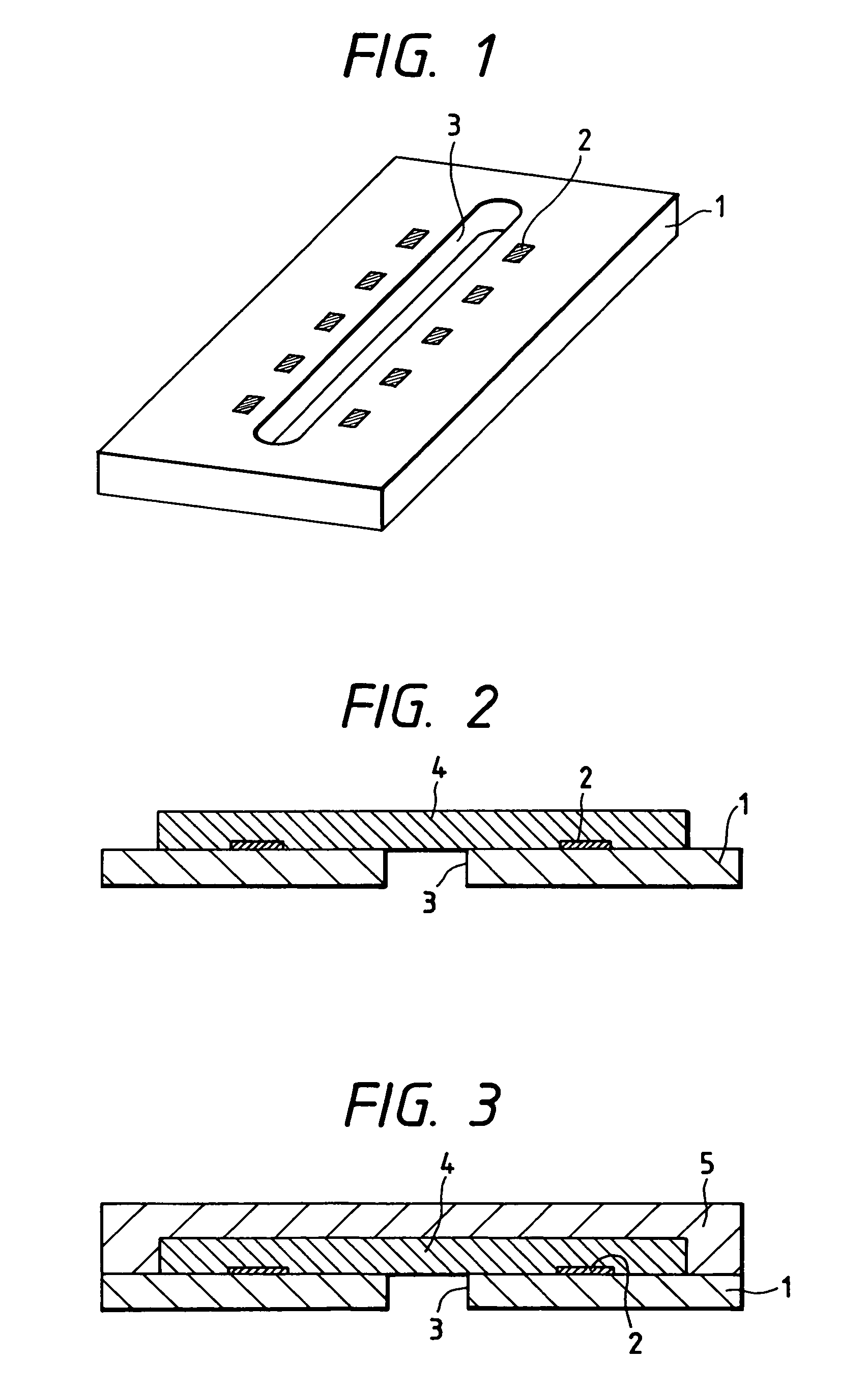
[0073]Onto a silicon wafer 1 having a thermal oxidized SiO2 film, electrothermal transducer elements (heaters composed of HfB2) 2 and an ink-supplying opening 3 were formed as shown in FIG. 1. Separately, a dry film was prepared, as a soluble resin layer, by applying polymethyl isopropyl ketone (ODUR-1010, produced by Tokyo Ohka Kogyo Co., Ltd.) onto a PET sheet and drying it. The ODUR was concentrated before use. This dry film was transferred and laminated onto the above silicon wafer. The laminated matter was baked at 120° C. for 20 minutes, and then was exposed for 1.5 minutes in a pattern of an ink flow path by means of a mask aligner PLA 520 with cold mirror CM 290 (manufactured by Canon K.K.). The pattern was developed with a mixture of methyl isobutyl ketone and xylene (mixing ratio of 2:1 by weight), and rinsed with xylene. The resist pattern 4 is formed and kept remained for securing the ink flow path between the ink-supplying opening 3 and the electrothermal transducers 2 ...

example 2

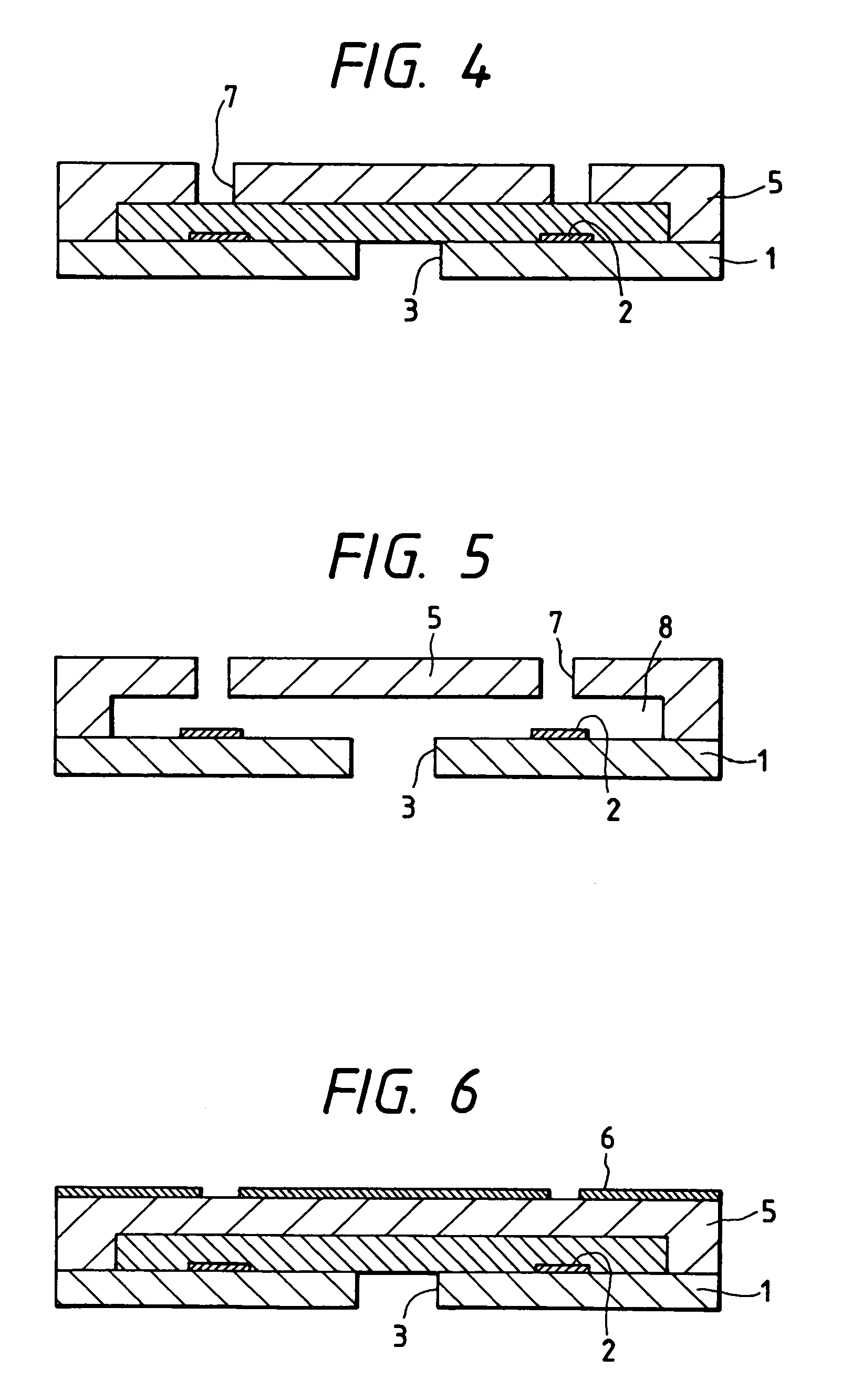
[0079]An ink flow path pattern 4 was formed through the same steps in the same manner as in Example 1. Onto the ink flow path pattern 4, a coating resin layer was formed by applying a solution of the composition shown in Table 2 in a mixed solvent of methyl isobutyl ketone and xylene by spin coating. The cationic polymerization initiator SP170 serves to initiate cationic polymerization by light irradiation, and copper triflate was used as an accelerator for the cationic polymerization.

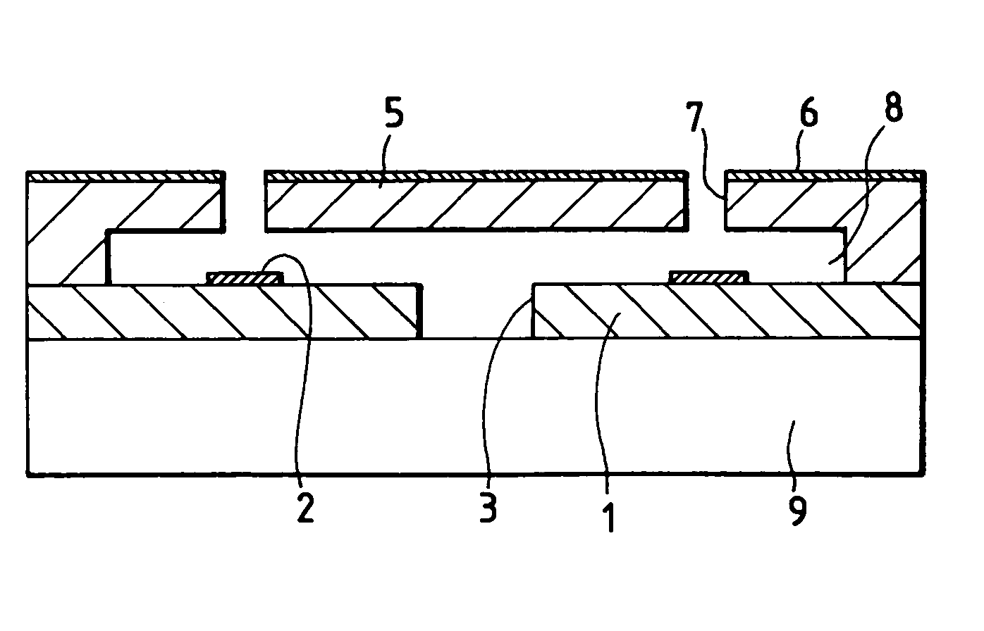
[0080]Since the composition shown in Table 2 has negative photosensitivity, light exposure was conducted with a mask shielding the discharge opening portions by means of a mask aligner MPA 600 (manufactured by Canon K.K.) at exposure light quantity of 3.5 J / cm2. After the light exposure, the composition was baked at 90° C. for 10 minutes, developed by a mixed solvent of methyl isobutyl ketone and xylene, and rinsed with xylene. The discharge openings were 20 μm in diameter, and the coating resin layer ...

example 3

[0082]A liquid jet recording head was prepared in the same manner as in Example 2 except that the coating resin layer was formed from the composition shown in Table 2.


PUM

PropertyMeasurementUnit
thicknessaaaaaaaaaa
pressure cooker testaaaaaaaaaa
thicknessaaaaaaaaaa

Abstract

A liquid jet recording head comprises a constituting member formed from a cured product of a resin composition comprising (1) a curable epoxy compound, (2) a compound having a functional group reactive to the curable epoxy compound and a fluorocarbon moiety, and (3) a curing agent.

Description

BACKGROUND OF THE INVENTION[0001]1. Field of the Invention[0002]The present invention relates to a liquid jet recording head for discharging droplets of recording liquid in an ink jet recording system.[0003]2. Related Background Art[0004]A liquid jet recording head used in an ink jet recording apparatus (liquid jet recording system) has generally a fine recording liquid discharge opening (hereinafter often referred to as an “orifice”), a liquid flow path, and an energy-generating device provided in the liquid flow path for generating energy for discharging the liquid. Such a liquid jet recording head is conventionally produced by forming a fine groove on a glass or metal plate by cutting, etching, or a like working method, and then bonding the grooved plate to another suitable plate to form a liquid flow path.[0005]However, the working precision is limited in cutting or etching of the glass plate or the metal plate. Moreover, the liquid jet recording heads produced by such a convent...

Claims


Application Information

Patent Timeline
Patent Type & Authority Patents(United States)
IPC IPC(8): B41J2/05B41J2/14B41J2/16C08G59/40C08G59/68
CPCB41J2/14032B41J2/1603B41J2/1628B41J2/1645B41J2/1634B41J2/1639B41J2/1631B41J2/135
Inventor OHKUMA, NORIOMIYAGAWA, MASASHITOSHIMA, HIROAKI
Owner CANON KK
Why Eureka
Try Eureka