Personal watercraft

a watercraft and propulsion technology, applied in special purpose vessels, steam power plants, vessel construction, etc., can solve the problems of insufficient taken-in air within the engine, inability to achieve desired performance, and difficulty in taking in a large amount of air through these gaps, so as to achieve smooth air taking a large amount of air and sufficient air

Inactive Publication Date: 2006-06-06
KAWASAKI HEAVY IND LTD
View PDF5 Cites 3 Cited by
  • Summary
  • Abstract
  • Description
  • Claims
  • Application Information

AI Technical Summary

Benefits of technology

[0008]The present invention addresses the above described condition, and an object of the present invention is to provide a personal watercraft capable of smoothly taking a large amount of air into an engine room to allow an engine to obtain sufficient air even when the engine is operating at a high speed, without providing an intricate water-proofing structure.

Problems solved by technology

Both the gap between the seat and the deck and the gap between the cover of the compartment and the deck have a relatively small flow cross-sectional area of air, and it is therefore difficult to take in a large amount of air through these gaps.
Especially when the engine is operating at a high speed, the air taken in from outside the body into the engine room may be insufficient, and hence the taken-in air within the engine may be correspondingly insufficient.
Under this condition, the engine is incapable of achieving desired performance.
However, since the personal watercraft often travels in choppy water, the water tends to enter the engine room through such a gap.

Method used


Image

  • Personal watercraft
  • Personal watercraft
  • Personal watercraft

Examples


embodiment 1

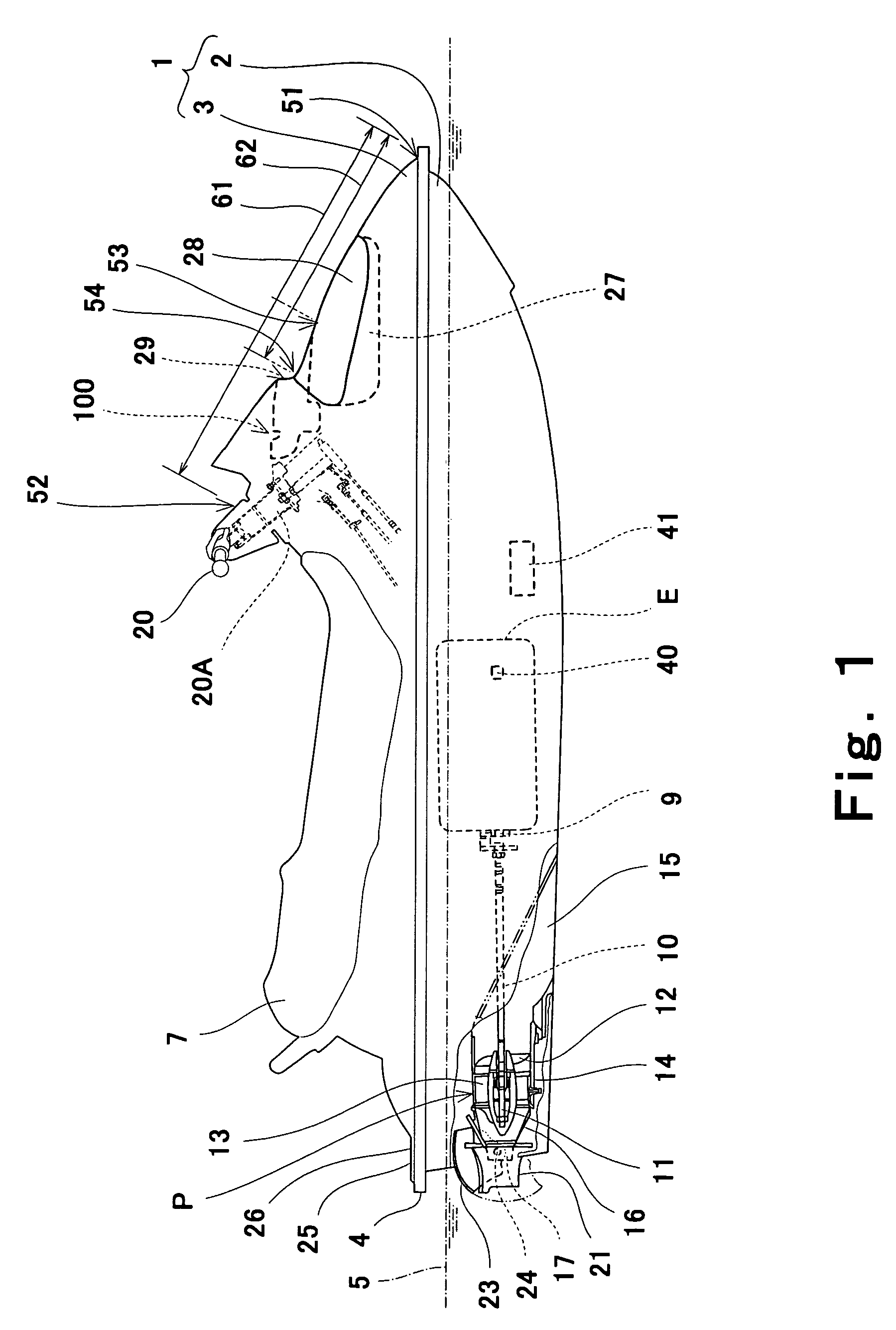
[0033]The personal watercraft in FIG. 1 is a straddle-type personal watercraft provided with a seat 7 straddled by a rider. A body 1 of the watercraft comprises a hull 2 and a deck 3 covering the hull 2 from above. A line at which the hull 2 and the deck 3 are connected over the entire perimeter thereof is called a gunnel line 4. In this embodiment, the personal watercraft is constructed such that a waterline 5 in a certain condition of the watercraft is located below the gunnel line 4.

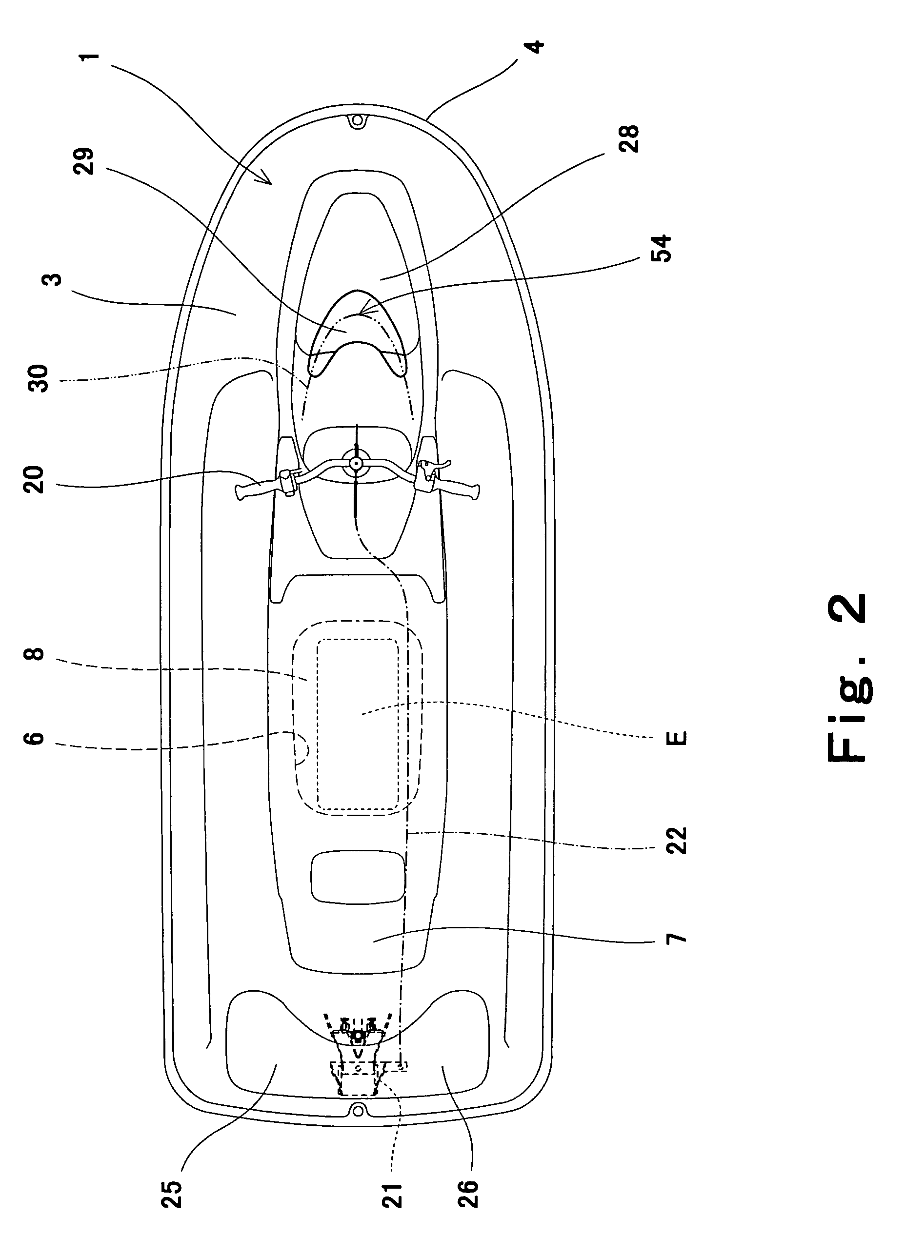
[0034]As shown in FIG. 2, an opening 6, which has a substantially rectangular shape as seen from above, is formed at a substantially center section of the deck 3 in the upper portion of the body 1 such that its longitudinal direction corresponds with the longitudinal direction of the body 1. The seat 7 is removably mounted over the opening 7.

[0035]An engine room 8 is provided in a space defined by the hull 2 and the deck 3 below the opening 6. An engine E is mounted within the engine room 8 and config...

embodiment 2

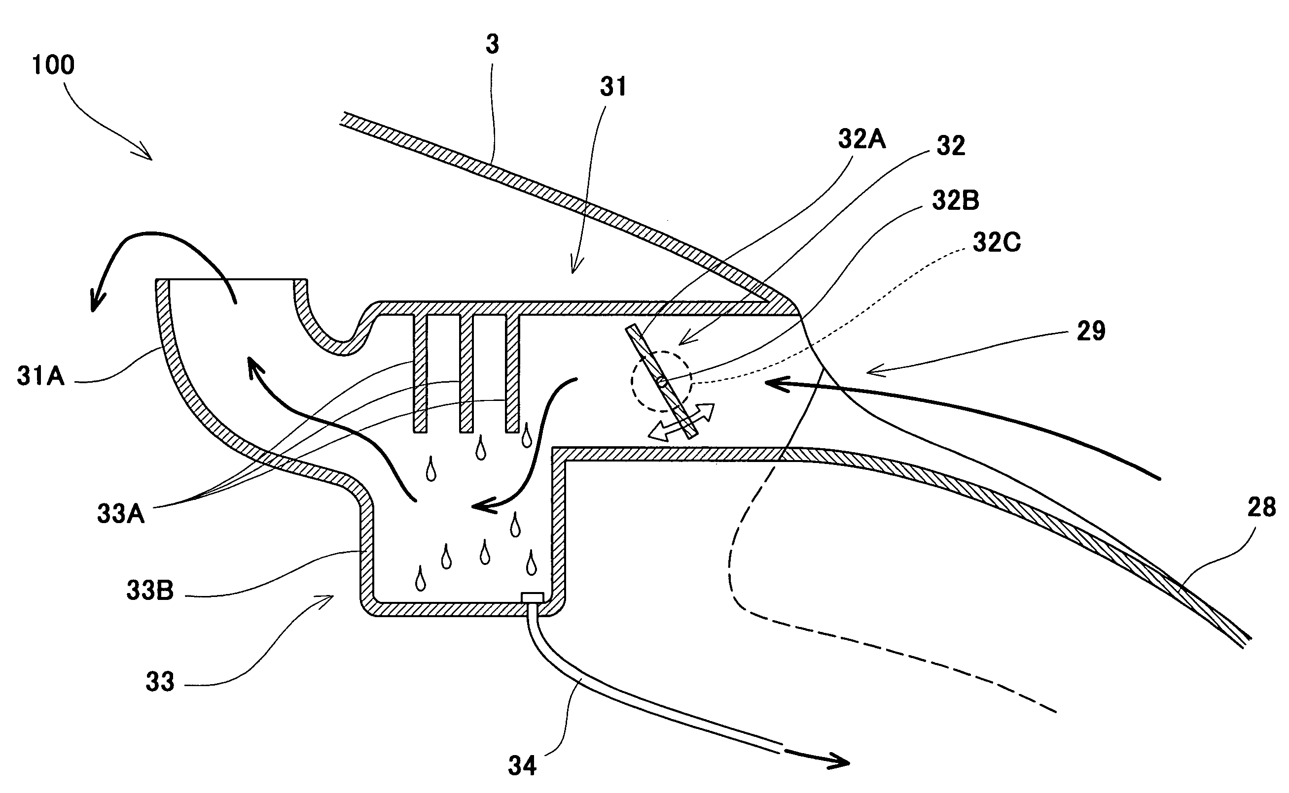
[0064]Referring to FIG. 4, an air-guiding system 200 having another configuration will be described. The air-guiding system 200 in FIG. 4 comprises an opening 60, an air-guiding pipe 31, a lead valve 61 as an openable valve, a filter 33, and the like.

[0065]In the air-guiding system 200 in FIG. 4, the opening 60 and the lead valve 61 replace the opening 29 and the butterfly valve 32 included in the air-guiding system 100 in FIG. 3. Therefore, hereinbelow, the opening 60 and the lead valve 61 will be described. The air-guiding system 200 is applicable to the personal watercraft in FIGS. 1 and 2.

[0066]As shown in FIG. 4, the air-guiding pipe 31 extends rearward from the opening 60 inside the body 1. A lower portion of the opening 60, i.e., a portion connecting the upper surface of the deck 3 which is located in front of the opening 60 to the inner surface of the lower portion of the air-guiding pipe 31 is curved forwardly and downwardly as in the structure shown in FIG. 3. A protruding...

embodiment 3

[0072]FIG. 5 is a partial side view of an air-guiding system 300 configured to penetrate a compartment 27 provided in the front portion of the deck 3 and a hatch cover 70 that covers an entrance to the compartment 27. The air-guiding system 300 is applicable to the personal watercraft in FIGS. 1 and 2.

[0073]As shown in FIG. 5, the hatch cover 70 is mounted pivotally around a pivot axis 71 on the deck 3. By pivoting the hatch cover 70 around the pivot axis 71, the entrance of the compartment 27 is opened and closed. A first opening 72 is provided in the hatch cover 70. A protruding portion 73 is provided on an upper edge portion of the first opening 72 to protrude forward and upward, as seen in a side view.

[0074]An air-guiding pipe 74 extends from the first opening 72 to an inside of the engine room 8. The air-guiding pipe 74 is comprised of a first air-guiding pipe 75 provided in the hatch cover 70 and located forward and a second air-guiding pipe 76 provided in the deck 3 and locat...


PUM


Abstract

A water-jet personal watercraft comprises a body including a hull and a deck covering the hull from above, the body being configured to form an engine room inside thereof in which an engine is mounted, and the deck being provided with a first opening configured to guide air from outside into the engine room, and a steering handle provided on an upper portion of the body, the steering handle including a steering shaft having a base portion where the steering shaft intersects an upper surface of the deck, wherein the first opening is provided on the upper surface of the deck at a position defined between the base portion of the steering shaft and a substantially center position between a front end portion of the body and the base portion of the steering shaft.

Description

BACKGROUND OF THE INVENTION[0001]1. Field of the Invention[0002]The present invention relates to a water-jet propulsion personal watercraft (PWC). More particularly, the present invention relates to an air-guiding system configured to guide ambient air from outside the watercraft into a body of the watercraft.[0003]2. Description of the Related Art[0004]In recent years, water-jet propulsion personal watercraft have been widely used in leisure, sport, rescue activities, and the like. The personal watercraft comprises a body including a hull and a deck covering the hull from above, and is provided with a straddle-type seat mounted over the deck. An opening is formed in the deck below the seat and configured to communicate with an inside of the body. A space within the body below the opening forms an engine room.[0005]An engine is mounted within the engine room and configured to drive a water jet pump that propels the watercraft. The personal watercraft is configured to take air into t...

Claims


Application Information

Patent Timeline
Patent Type & Authority Patents(United States)
IPC IPC(8): B63H21/10B63H11/08B63B35/73B63J2/06
CPCB63J2/06B63B35/731B63B34/10
Inventor MATSUDA, YOSHIMOTO
Owner KAWASAKI HEAVY IND LTD
Why Eureka
Try Eureka