Tissue anchor system

a technology of tissue anchors and stents, which is applied in the direction of prosthesis, surgical staples, surgical forceps, etc., can solve the problems of leaking of urine, loss of bladder neck support, and disabling sui

Inactive Publication Date: 2006-06-06
WALSHE CHRISTOPHER J
View PDF68 Cites 231 Cited by
  • Summary
  • Abstract
  • Description
  • Claims
  • Application Information

AI Technical Summary

Benefits of technology

[0018]It is an object of the invention to provide an adjustable tissue-anchoring device to adjust the placement of devices or tissues attached to the anchor postoperatively without further invasive surgery.

Problems solved by technology

Urinary incontinence is an involuntary release of urine when increases in abdominal pressure, caused by sneezing, coughing, or exercising, are not uniformly transmitted to the proximal urethra, resulting in urine “leakage.” Moderate stress urinary incontinence (“SUI”) is inconvenient and can be a social and hygienic problem, while severe SUI can be disabling.
Several defects can result in loss of support of the bladder neck.
For instance, one example of passive support failure is paravaginal “defects” caused by separation of the vaginal wall from the pelvis caused by breakage or stretching of connective tissue (pelvic organ prolapse).
Such separation results in downward rotation of the vaginal wall, which in turn results in downward rotation of the bladder neck because the bladder is partially supported by the vagina.
Loss of muscle tone may result in downward rotation of the bladder.
Problems associated with surgical correction of the failed support mechanisms include under- or over-correction of the UVJ.
Too much elevation can result in voiding dysfunction (reduced capacity or inability to void), prolonged catheterization, and the need for postoperative correction.

Method used


Image

  • Tissue anchor system
  • Tissue anchor system
  • Tissue anchor system

Examples


Embodiment Construction

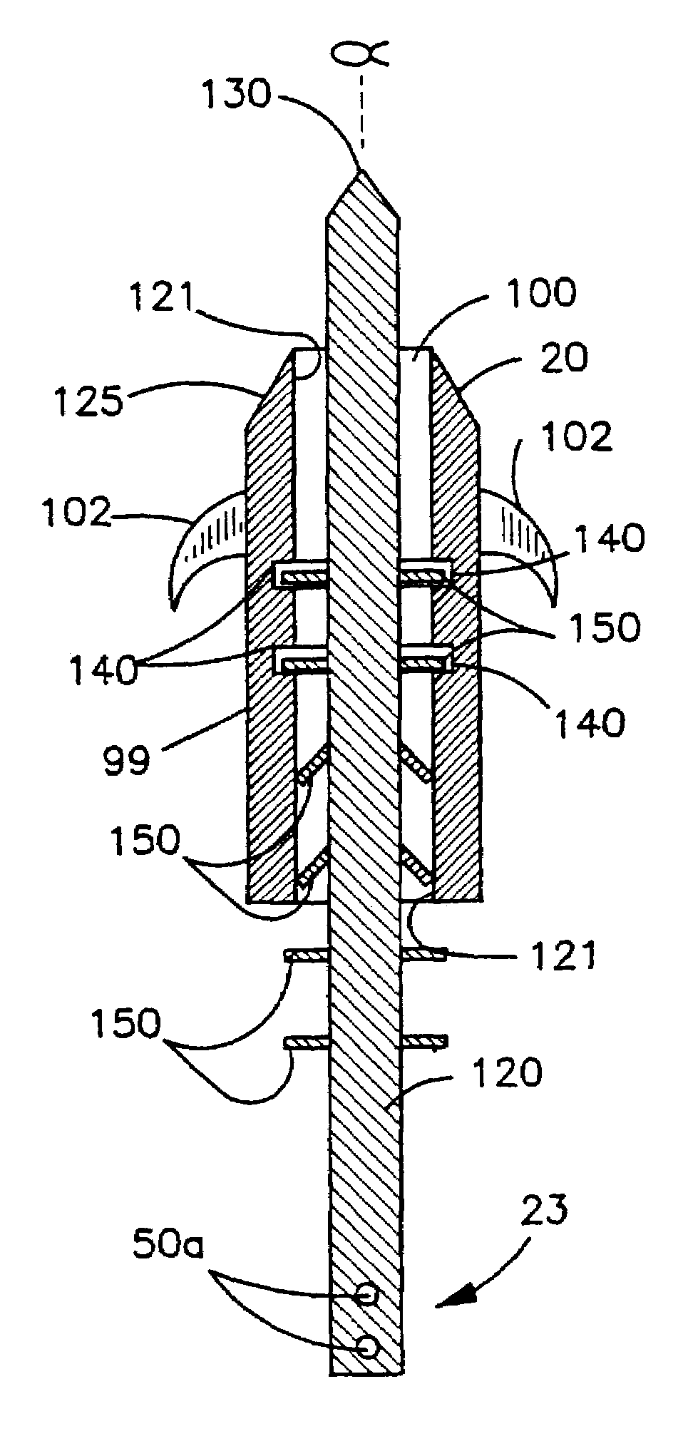
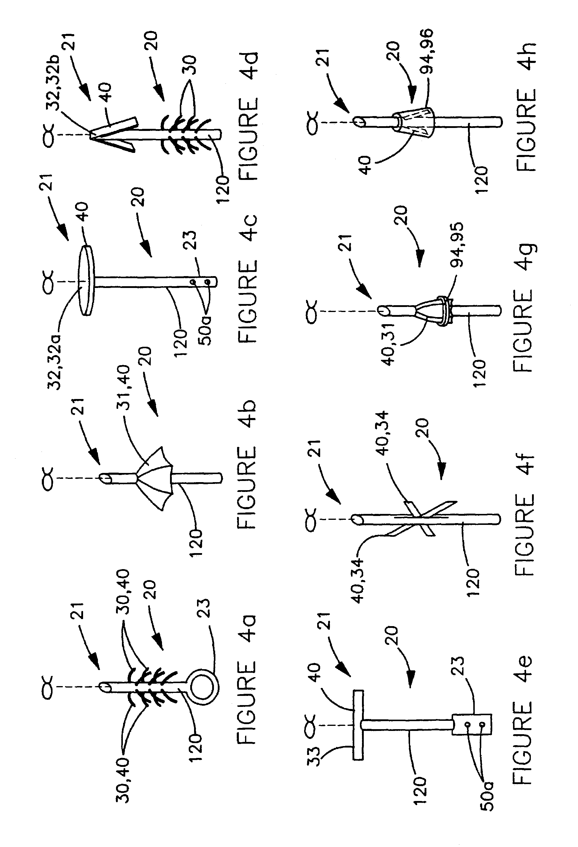
[0069]Illustrations of construction, design, and methods of operation of the invention are set forth below with specific references to the Figures. However, it is not the intention of the inventor that the scope of his invention be limited to these embodiments.

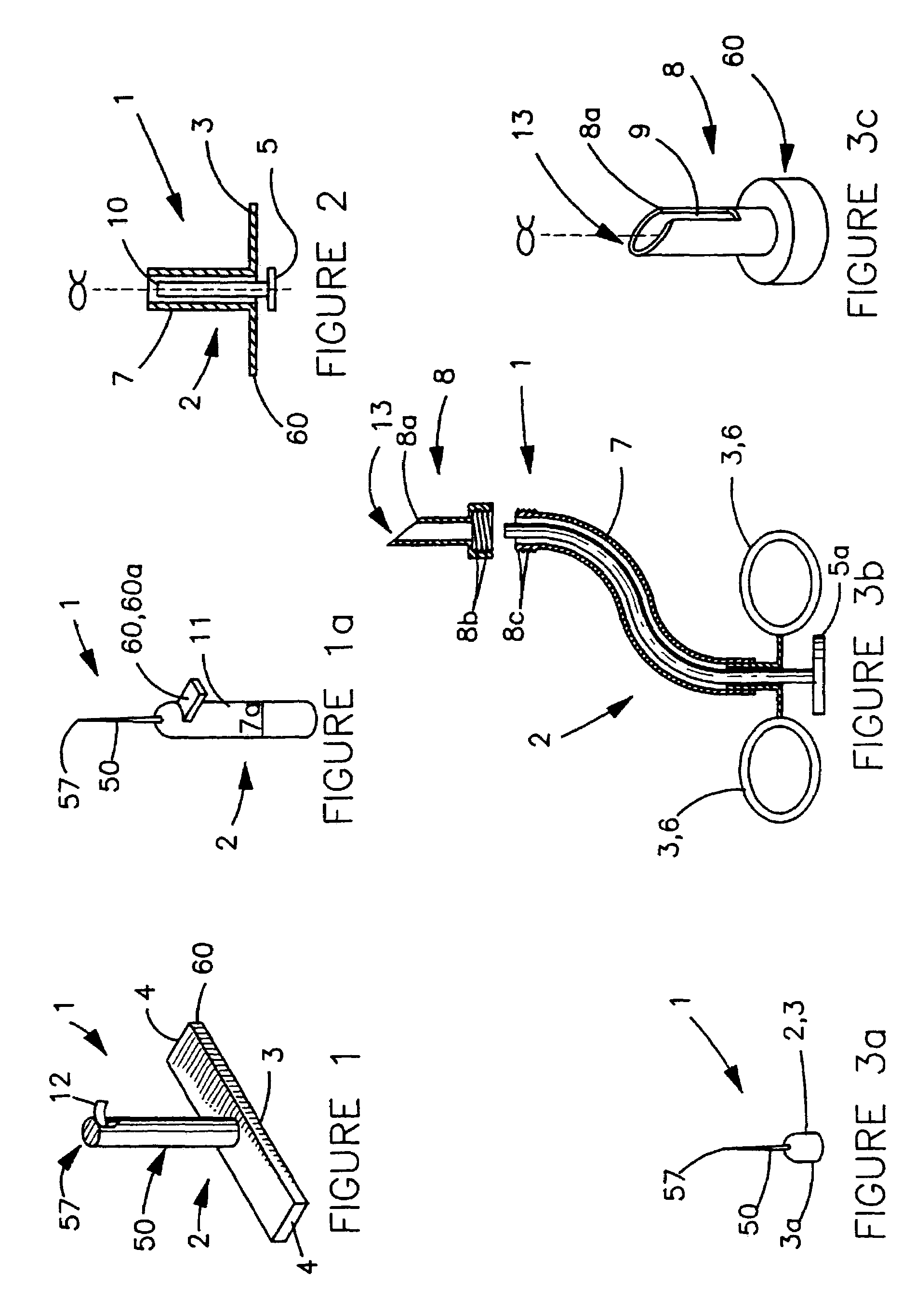
[0070]FIG. 1 illustrates one embodiment of the tissue-anchor delivery device 1. Delivery device 1 comprises a housing 2 and one or more finger grips 3, which comprise flats 4 on opposing sides of housing 2 designed to enable a surgeon to hold device 1. Finger grips 3 may be rings 6 (see FIG. 3b) through which the surgeon inserts fingers, a thimble (see FIG. 3a), a handgrip, or any other shape that enables a surgeon to hold delivery device 1. Finger grips 3 are unnecessary if housing 2 is adapted to be hand-held, such as a pen-shaped housing 11 shown in FIG. 1a.

[0071]FIGS. 1a and 3a illustrate an anchor stay 50. Anchor stay 50 comprises a portion of housing 2 adapted to retain an anchor 20 (not shown) thereto, as described bel...


PUM


Abstract

The invention disclosed herein is a tissue-anchoring system, including a tissue-anchoring device and tissue anchors. The tissue-anchoring device includes a housing and a tissue anchor positioned on the tissue-anchoring device that will be inserted into a tissue or secured onto a tissue. The device may optionally have a plunger assembly slidably positioned in the housing to assist advancing anchor into a tissue. The tissue anchor has a barb end and a shaft. The barb end is adapted to resist removal from a tissue after the anchor has been inserted. The tissue anchor shaft and the barb end may be hollow. The anchor shaft has an attachment member distal from the barb end for direct attachment to a tissue or for attachment of sutures or slings. The tissue anchors may include an adjustment mechanism for intra- or post-operative adjustments.

Description

TECHNICAL FIELD[0001]This application is a continuation of U.S. patent application Ser. No. 09 / 716,851, which was filed on Nov. 17, 2000, now U.S. Pat. No. 6,506,190, and which claims priority to International Application number PCT / US99 / 11225, which was filed on May 21, 1999 and which claims priority to U.S. Provisional Application No. 60 / 086,284, filed on May 21, 1998. This invention relates to a tissue anchor and applicator for supporting a suture, sling member, or other device for use in a surgical procedure. In particular, this invention relates to tissue anchors for use in surgical treatment of urinary incontinence.BACKGROUND ART[0002]One problem this invention intends to address is urinary incontinence, but the invention is applicable to a broader range of problems. The background, however, will discuss urinary incontinence as an example.[0003]Urinary incontinence is an involuntary release of urine when increases in abdominal pressure, caused by sneezing, coughing, or exercis...

Claims


Application Information

Patent Timeline
Patent Type & Authority Patents(United States)
IPC IPC(8): A61B17/04A61B17/00A61B17/28
CPCA61B17/0401A61B2017/00805A61B2017/0409A61B2017/0412A61B2017/0414A61B2017/2911A61B2017/0427A61B2017/0435A61B2017/0437A61B2017/044A61B2017/2905A61B2017/0417
Inventor WALSHE, CHRISTOPHER J.
Owner WALSHE CHRISTOPHER J
Why Eureka
Try Eureka