Radiation barrier

a technology of radiation barriers and barriers, applied in the field of radiation barriers, can solve the problems of medical personnel being exposed to radiation, being exposed to significant cumulative radiation doses, and being exposed to radiation reflected or scattered by objects,

Active Publication Date: 2006-06-06
ECO CATH LAB SYST
View PDF52 Cites 34 Cited by
  • Summary
  • Abstract
  • Description
  • Claims
  • Application Information

AI Technical Summary

Benefits of technology

[0005]In another aspect, the present invention includes a wall for shielding a person from radiation emitted from a radiation source. The wall includes a radiopaque lower section and a radiopaque upper section mountable on the lower section. The upper section has an opening sized and shaped for accommodating a portion of a table for supporting a patient and a portion of the patient supported by the table. The upper section and the lower section are positionable between the radiation source and the person to prevent radiation from traveling directly between the radiation source and the person.
[0007]In another aspect, the present invention includes a radiation barrier for shielding a person from radiation emitted from a radiation source. The barrier includes a radiopaque wall positionable between the radiation source and the person to prevent radiation from traveling directly between the radiation source and the person. The wall has an opening for accommodating a portion of the radiation source and a radiopaque cover positioned over the opening for preventing radiation emitted from the radiation source from passing through the opening to the person.

Problems solved by technology

Medical personnel are exposed to radiation during these procedures.
Exposure to radiation over extended periods of time, even if the exposure is to low level radiation, may be toxic and cause a wide variety of health problems.
However, medical personnel may perform many procedures per year over many years, and therefore may be exposed to significant cumulative radiation doses over time.
However, medical personnel may still be exposed to radiation reflected or scattered by objects, such as the table supporting the patient, the walls of the room, and even the patient.
However, the lead aprons, collars and glasses may not fully protect the personnel as substantial portions of legs, arms, and head remain exposed.
Thus, despite the use of radiation protection clothing and shields, medical personnel may be exposed to amounts of radiation over time that harm the personnel.
Additionally, the lead aprons and other radiation protection clothing is often very heavy, possibly leading to long term health problems such as disabling spinal injury.

Method used


Image

  • Radiation barrier
  • Radiation barrier
  • Radiation barrier

Examples


Embodiment Construction

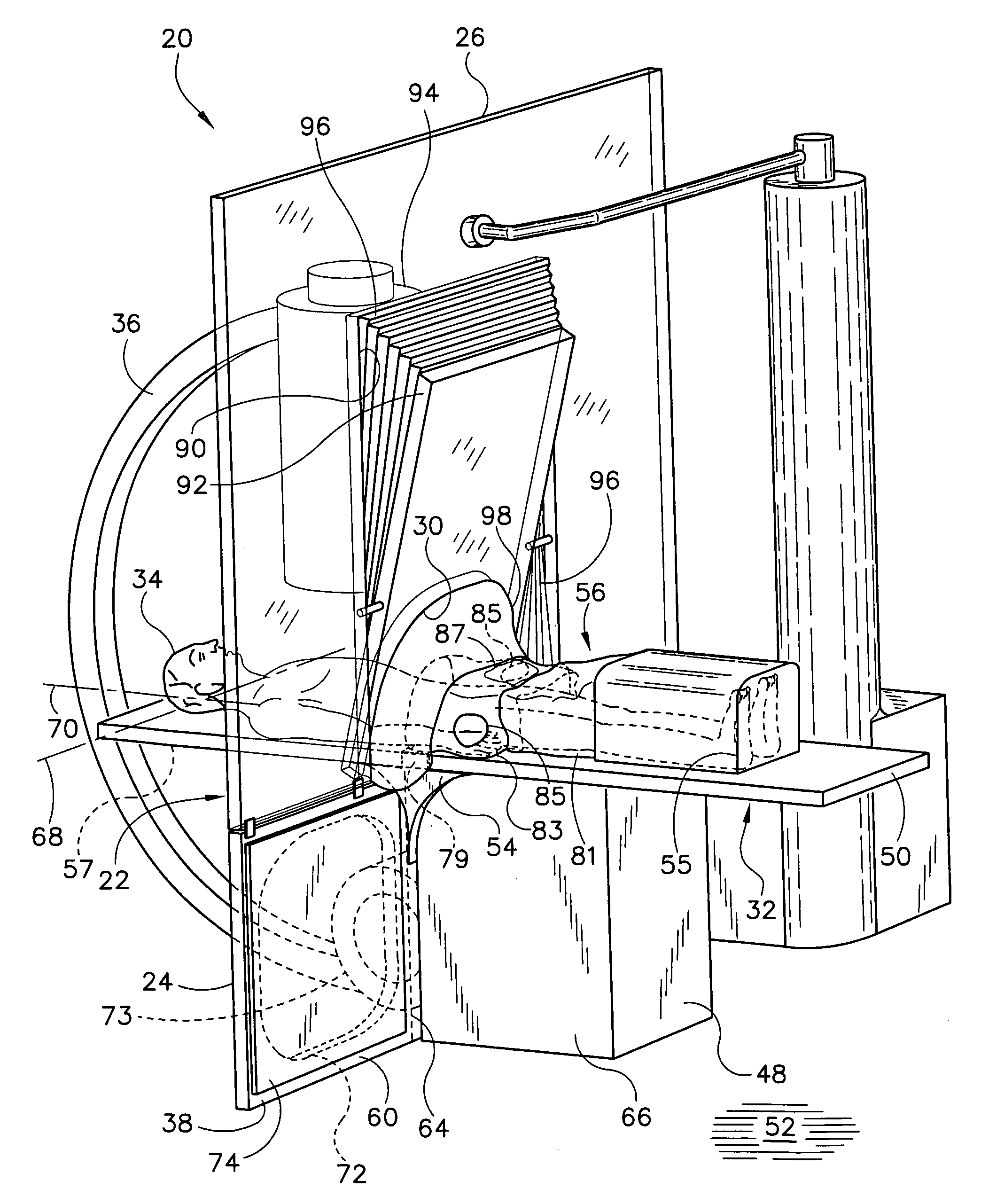
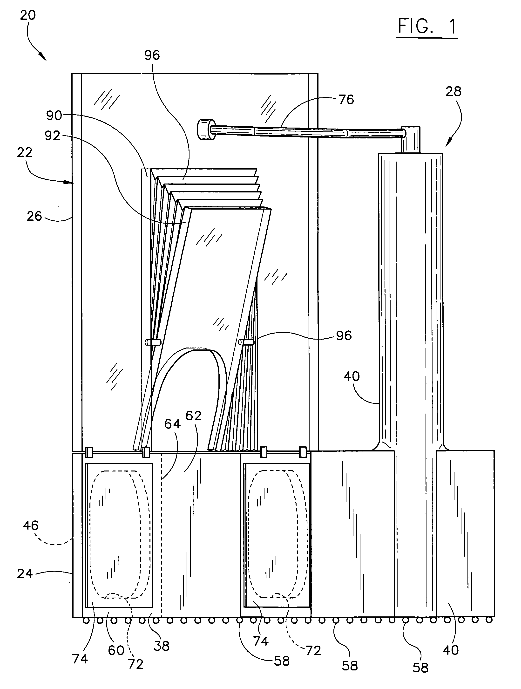
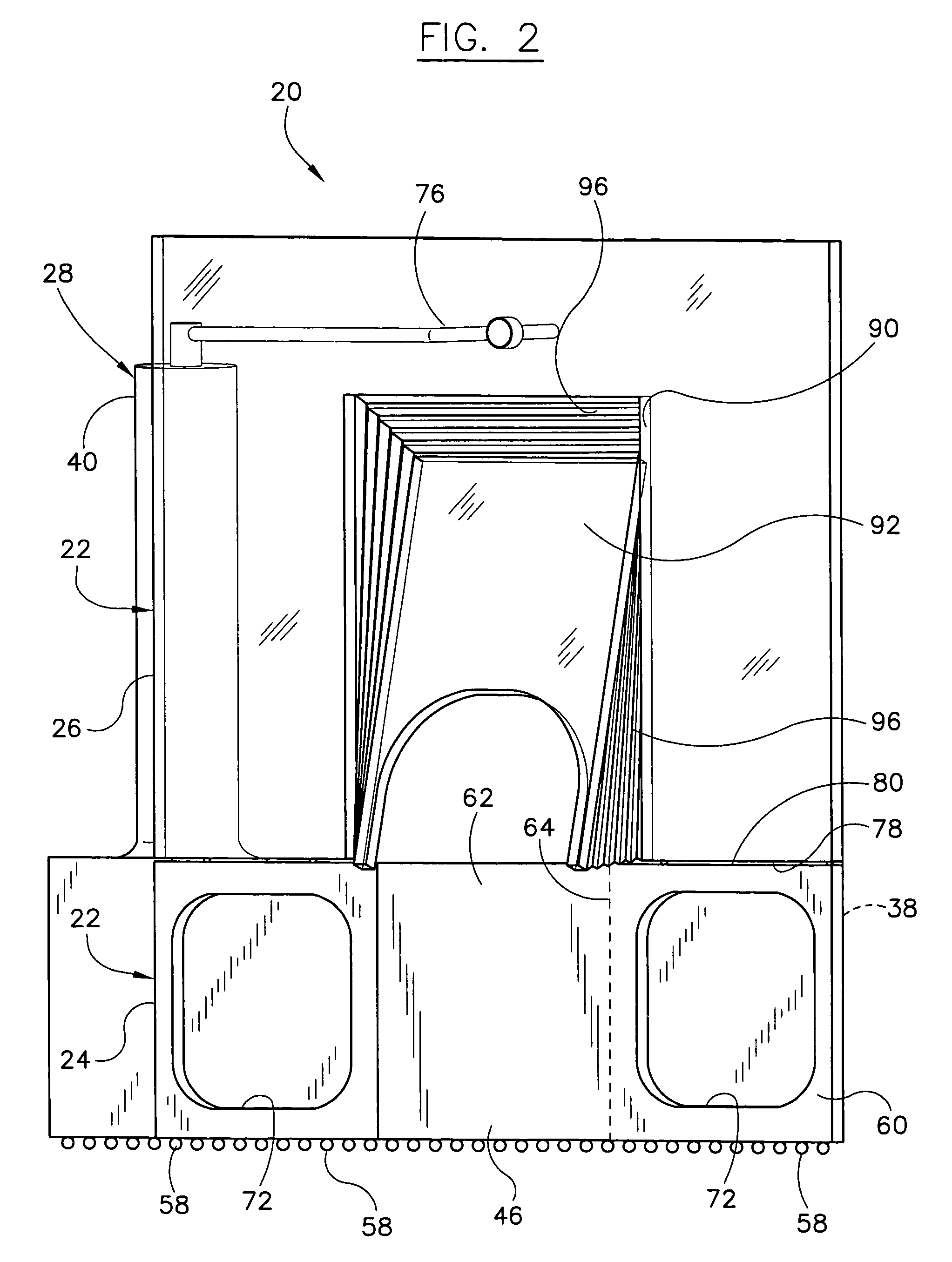
[0029]Referring now to the drawings, and more specifically to FIGS. 1 and 2, a radiation barrier of a first embodiment of the present invention is designated in its entirety by the reference numeral 20. The barrier 20 includes a radiopaque wall, generally designated by 22, having a radiopaque lower section 24 and a radiopaque upper section 26 detachably mountable on the lower section. As used herein, the term “radiopaque” is intended to mean generally opaque to various forms of radiation. Although other equivalencies may be used without departing from the scope of the present invention, in one embodiment “radiopaque” is intended to mean something having a lead equivalence of at least about 0.3 mm (i.e., capable of blocking as much radiation as a sheet of lead about 0.3 mm thick). A support, generally designated by 28, is attached to the upper section 26 and the lower section 24 for supporting the upper and lower sections. As illustrated in FIG. 3, the wall 22, and more specifically ...


PUM


Abstract

A radiation barrier for shielding a person from radiation emitted from a radiation source. The barrier includes a radiopaque wall extending between opposite lateral edges, wherein the wall is positionable between the radiation source and the person to prevent radiation from traveling directly between the radiation source and the person, and a radiopaque deflector extending from the wall and obliquely angled relative to the wall.

Description

BACKGROUND OF THE INVENTION[0001]The present invention relates generally to radiation barriers, and more specifically to radiation barriers for shielding a person from radiation emitted during a medical procedure.[0002]Radiation is emitted from equipment used in a wide variety of medical procedures. For example, radiation is emitted by radiographic or x-ray machines used by cardiologists when performing angioplasty procedures. Medical personnel are exposed to radiation during these procedures. Exposure to radiation over extended periods of time, even if the exposure is to low level radiation, may be toxic and cause a wide variety of health problems. Because patients undergo a limited number of exposures, cumulative radiation exposure is rarely a significant health concern to patients. However, medical personnel may perform many procedures per year over many years, and therefore may be exposed to significant cumulative radiation doses over time.[0003]To reduce exposure, both fixed an...

Claims


Application Information

Patent Timeline
Patent Type & Authority Patents(United States)
IPC IPC(8): G21C11/00G02B5/00G21F1/00H01J1/52
CPCA61B6/107G21F3/00G21Y2004/30G21Y2002/304G21Y2002/501G21Y2002/201
Inventor GOLDSTEIN, JAMES A.
Owner ECO CATH LAB SYST
Why Eureka
Try Eureka