Antenna connector for hazardous area

a technology for connecting antennas and hazardous areas, applied in the direction of antenna details, antennas, basic electric elements, etc., can solve the problems of high inflexibility, high cost, time-consuming, and laborious, and achieve the effect of simple, inexpensive, and quick matter, and easy and quick connection

Active Publication Date: 2006-06-06
SOLEXY USA
View PDF4 Cites 33 Cited by
  • Summary
  • Abstract
  • Description
  • Claims
  • Application Information

AI Technical Summary

Benefits of technology

[0007]The present invention provides an intrinsically safe, explosion-proof antenna fitting which may be threaded directly into an explosion-proof enclosure, a safe area enclosure, or an electrical conduit, without the need for further sealing fittings required at the connection point with the antenna fitting. A standard antenna may then be connected to the receptacle projecting from the antenna fitting. Should the antenna become damaged or in need of replacement, it is a simple, inexpensive, and quick matter to unscrew the old standard antenna and replace it with a new one or one of the correct length.
[0008]In a preferred embodiment, the antenna fitting is made of a corrosion resistant grade of stainless steel, threaded at one end for screwing into the enclosure or conduit. The antenna fitting defines a hollow cavity. Inside this cavity, a circuit board with a capacitive block circuit provides the intrinsically safe barrier. The cavity is then filled with a two-part compound. The first compound is a hazardous area sealing compound to withstand the expected force of an explosion. The second compound is an electrical potting compound which surrounds the capacitive block circuit and serves as an electrical insulator, protects the components from moisture, and provides strain relief for the coaxial cable projecting from a first end of the fitting. This coaxial cable connects to a radio transmitter or a receiver. Projecting from a second end of the fitting is a standard, reverse polarity SMA receptacle antenna connector to which a standard antenna may be easily and readily connected.
[0009]In a preferred embodiment, the circuit board components have a dielectric rating of 1500 volts and the capacitive block circuit prevents fault condition pass-through of alternating or direct current up to 250 volts. The circuit board components also provide a second function as they provide a means for optional radio attenuation if the radio transmits at too high a power level. This option can be jumpered out if the radio is internally attenuated.
[0010]In a preferred embodiment, the antenna fitting is designed to withstand a 6,000 PSIG hydraulic pressure test. Thus, the antenna fitting and the hazardous area sealing compound within the antenna fitting are designed to withstand the force of an explosion, eliminating the need for a separate potted sealing fitting at the point where the antenna fitting connects to the electrical conduit or to the electrical enclosure.

Problems solved by technology

The installation of sealing fittings is expensive, labor intensive, and time consuming (the sealing compound must be allowed to cure after it is injected into the sealing fitting).
This prior art method is highly inflexible.
If the encased antenna was incorrectly specified or supplied, or if the receiver or transmitter must be replaced with one of different frequency, or if the encased antenna is accidentally damaged, there is no simple manner to replace the antenna.
This is expensive and time consuming.

Method used


Image

  • Antenna connector for hazardous area
  • Antenna connector for hazardous area

Examples


Embodiment Construction

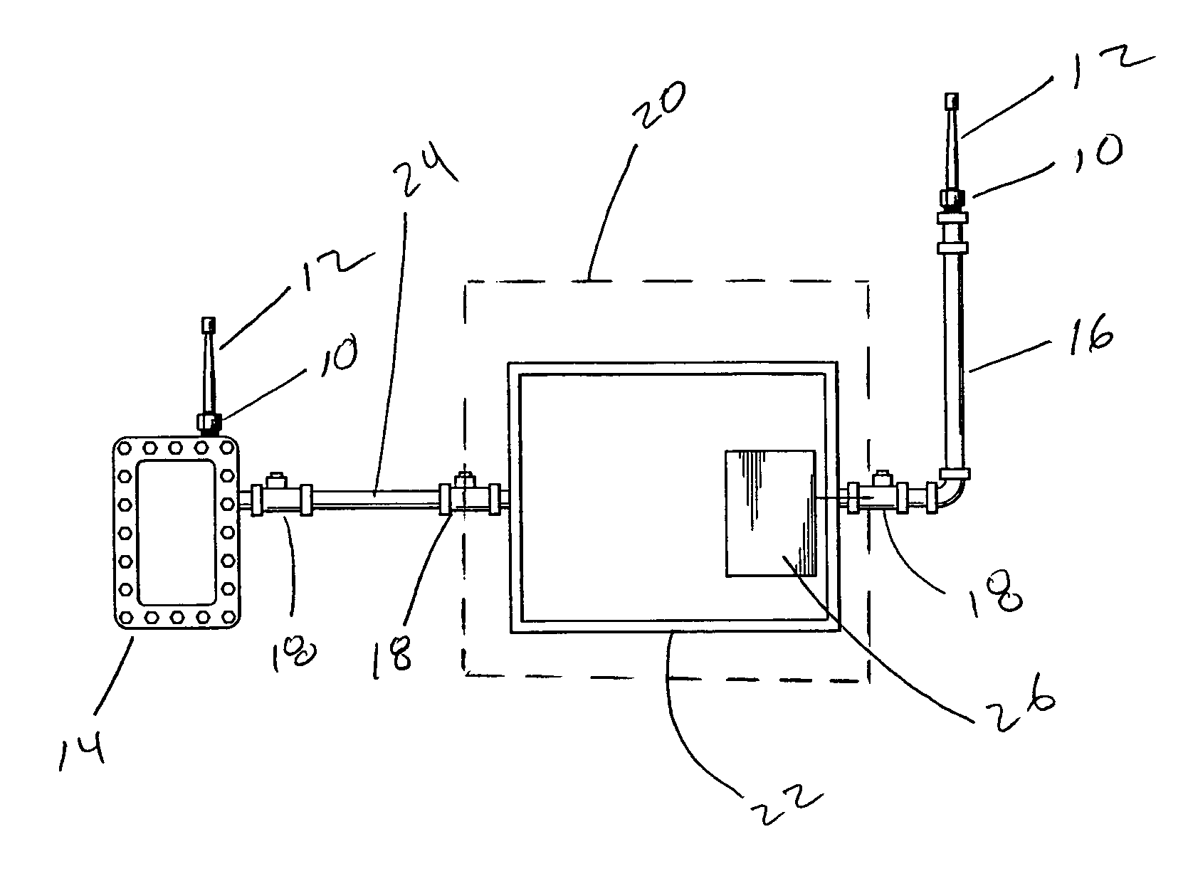
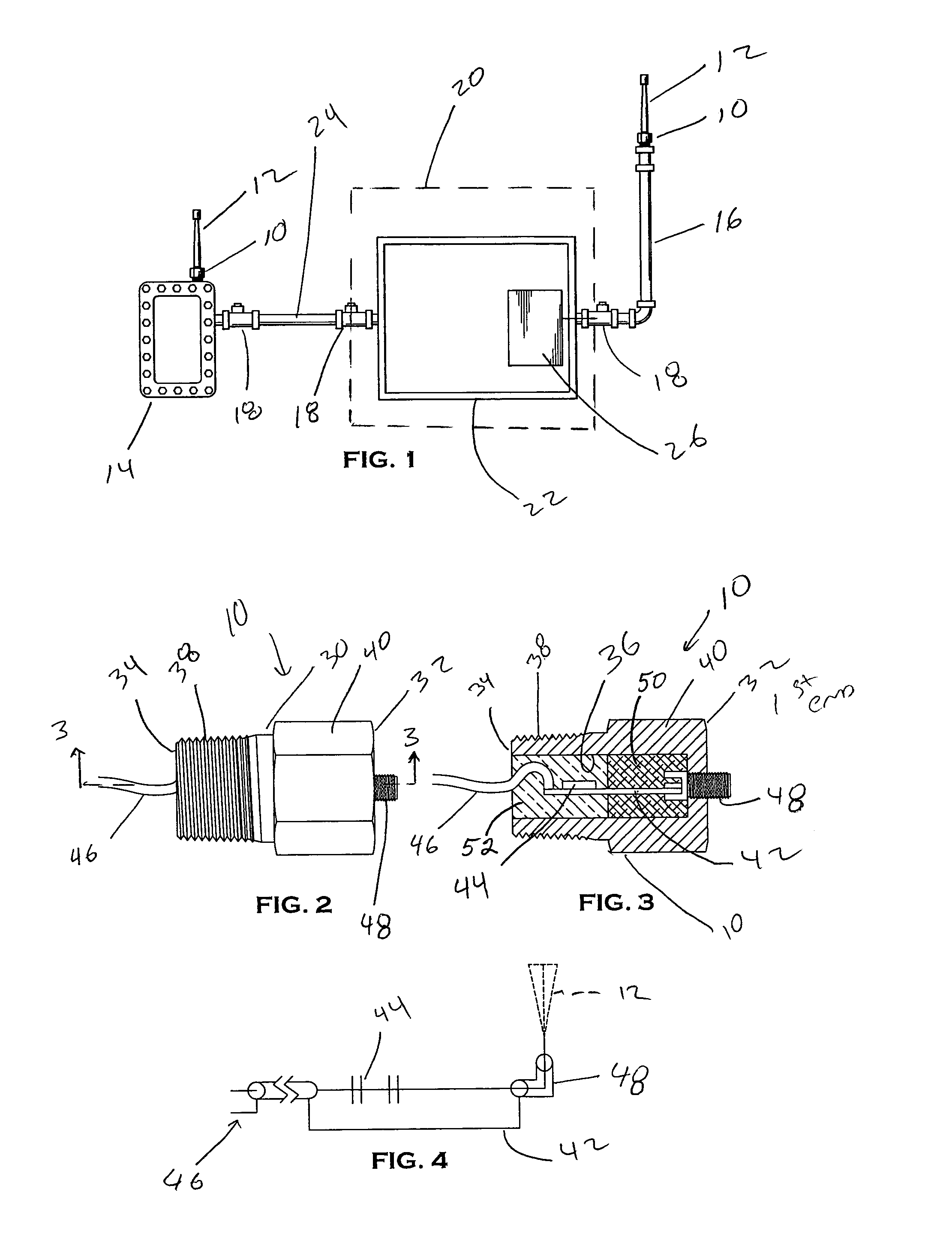
[0015]FIGS. 1–3 show an antenna fitting 10 for connecting an antenna 12 to an electrical enclosure 14 or to an electrical conduit 16. As discussed in more detail below, FIG. 3 shows a more detailed view of the antenna fitting 10 made in accordance with the present invention.

[0016]Referring now to FIG. 1, the area inside the dotted rectangle 20 represents an electrically safe area classification environment, while the area outside of the dotted rectangle represents an electrically hazardous area classification environment. Thus, the electrical enclosure 22 inside the safe area environment may be a conventional electrical enclosure, while the enclosure 14 is an explosion-proof enclosure 14 for use in an electrically hazardous area classification environment. As may be appreciated from this schematic, a standard antenna 12 may be mounted directly to the enclosure 14 via the antenna fitting 10 without the need for additional potted fittings such as the potted fittings 18 shown elsewhere...


PUM


Abstract

A device for connecting an antenna to a hazardous enclosure. The device includes an intrinsically safe barrier for protection against electrical surges, and an explosion-proof device enclosure to contain the force of an explosion.

Description

BACKGROUND OF THE INVENTION[0001]The present invention relates to a fitting for connecting an antenna. More particularly, it relates to a fitting for connecting an antenna in a hazardous area environment to an electrical enclosure such as an explosion-proof enclosure, a safe area enclosure, or to an electrical conduit.[0002]The length of an antenna depends on the frequency of the transmitted signal. Therefore, for different frequencies of transmission, and for different radio receivers and transmitters, it may be necessary to have different length antennas. Standards for installation of electrical equipment in hazardous area environments require that the installation comply with two types of protection:[0003]an intrinsically safe barrier which will suppress an electrical surge which may potentially travel through the device, and[0004]an explosion-proof device enclosure to withstand the maximum anticipated force of an explosion.[0005]Prior art methods for complying with these standar...

Claims


Application Information

Patent Timeline
Patent Type & Authority Patents(United States)
IPC IPC(8): H01Q1/50
CPCH01Q1/50H01Q1/002
Inventor WILLOUGHBY, CHRISPOPP, GREGGPETERS, MARK
Owner SOLEXY USA
Why Eureka
Try Eureka