Lithography tool test patterns and method

a lithography tool and electron beam technology, applied in the field of electron beam lithography tool resolution testing, can solve the problems of wasting lithography tool time and space in the test pattern, limiting performance, and often not providing insight in the resolution test pattern, so as to improve the accuracy of lithography tool resolution, and facilitate cleaving the lines

Inactive Publication Date: 2006-06-06
IBM CORP
View PDF6 Cites 12 Cited by
  • Summary
  • Abstract
  • Description
  • Claims
  • Application Information

AI Technical Summary

Benefits of technology

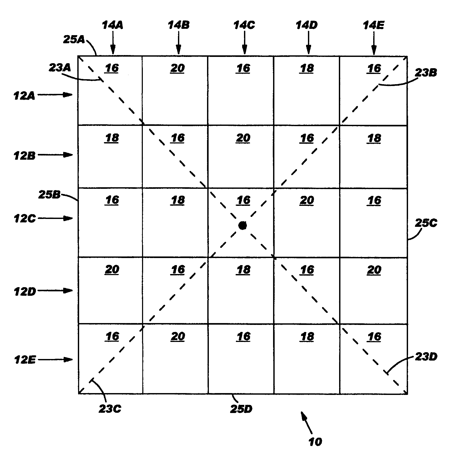
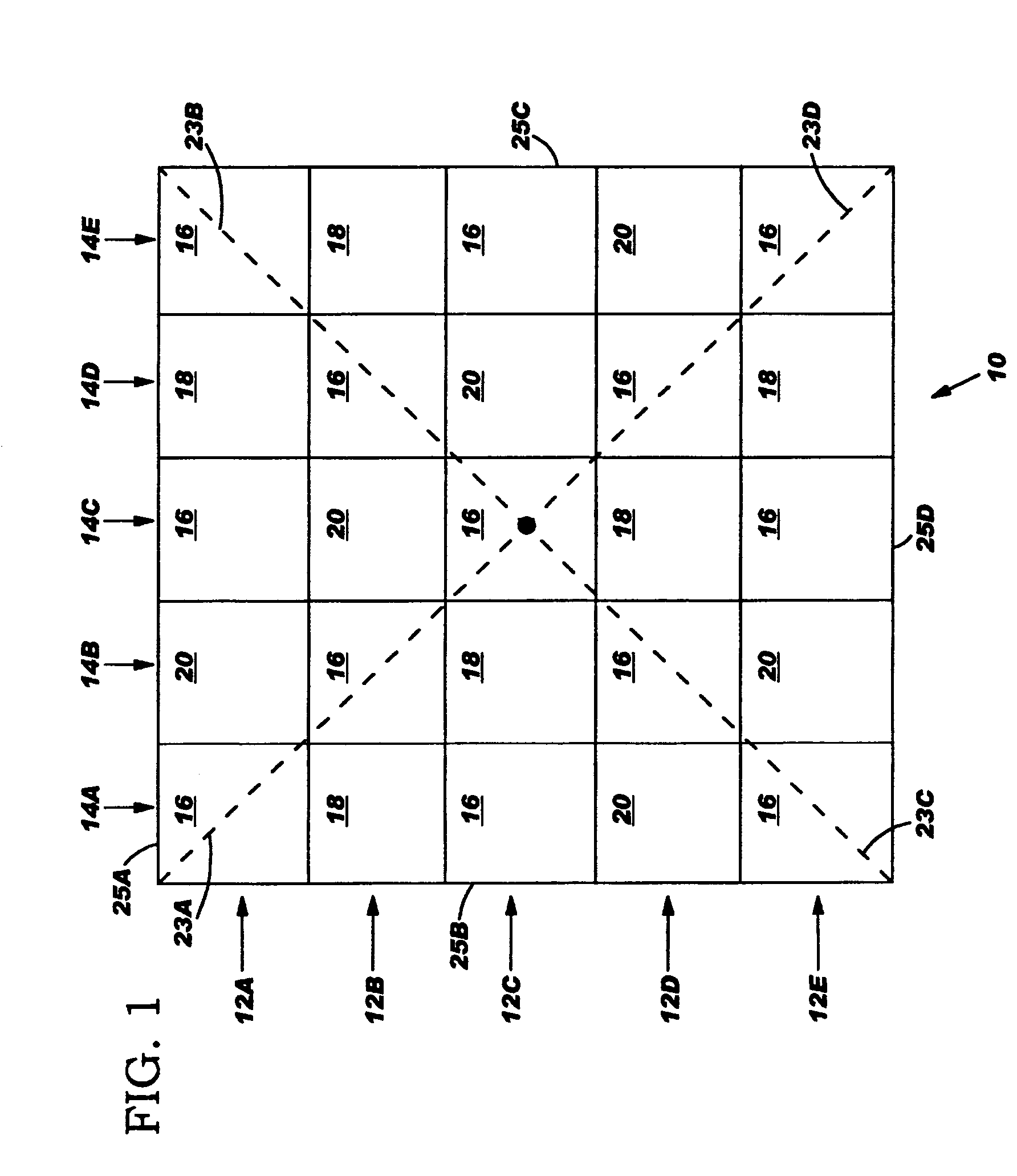
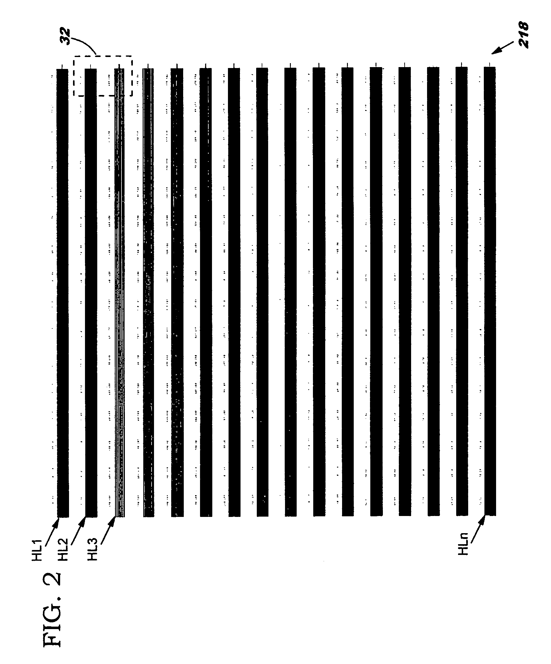
[0005]The invention provides a method and patterns for efficiently evaluating and adjusting the resolution of a lithography tool. In particular, a test pattern is provided that includes a feature pattern that is repeated in several different locations in the test pattern. In one embodiment, the feature pattern is located at the center of the test pattern, each corner of the test pattern, and the midpoints of each radius and side of the test pattern. The feature pattern can include sub-patterns that test multiple exposure characteristics of the lithography tool. For example, isolated lines, isolated spaces, and finger arrays can be provided as well as multiple sets of holes having positive tone and / or negative tone. The feature pattern can be interleaved in the test pattern with horizontal line patterns and vertical line patterns that are arranged throughout the test pattern to facilitate cleaving of the lines for three dimensional image analysis. A method of evaluating the lithography tool resolution is also presented in which the test pattern is exposed one or more times on a resist coated substrate by the lithography tool and one or more test pattern images are generated for analysis. Each exposure can use varying exposure conditions. Adjustments can be made to the lithography tool based on the analysis of the test pattern image(s). Correct exposure dosage conditions for resolution evaluation can be assured by comparing incorporated sets of positive and negative tone hole arrays.

Problems solved by technology

However, the resolution test pattern is often not designed to provide insight to the lithography tool factors that limit performance.
However, the current process wastes both lithography tool time as well as space in the test patterns.

Method used


Image

  • Lithography tool test patterns and method
  • Lithography tool test patterns and method
  • Lithography tool test patterns and method

Examples


Embodiment Construction

[0026]The invention provides a method and patterns for efficiently evaluating and adjusting the resolution of a lithography tool. In particular, a test pattern is provided that includes a feature pattern that is repeated in several different locations in the test pattern. In one embodiment, the feature pattern is located at the center of the test pattern, each corner of the test pattern, and the midpoints of each radius and side of the test pattern. The feature pattern can include sub-patterns that test multiple exposure characteristics of the lithography tool. For example, isolated lines, isolated spaces, and finger arrays can be provided as well as multiple sets of holes having positive tone and / or negative tone. The feature pattern can be interleaved in the test pattern with horizontal line patterns and vertical line patterns that are arranged throughout the test pattern to facilitate cleaving of the lines for three dimensional image analysis. A method of evaluating the lithograp...


PUM

PropertyMeasurementUnit
space widthsaaaaaaaaaa
sizesaaaaaaaaaa

Abstract

Test patterns and a method for evaluating and adjusting the resolution of an electron beam lithography tool. The test patterns include multiple feature patterns that are repeated throughout the test pattern. Each feature pattern can be interleaved with horizontal and/or vertical line patterns that facilitate cleaving of a test substrate for three dimensional analysis of the developed image. Further, each feature pattern can comprise multiple sub-patterns. Each sub-pattern includes at least one feature having a size that varies from less than a nominal resolution limit of the lithography tool to greater than the nominal resolution limit. The lithography tool resolution can be evaluated by exposing a test pattern on a resist coated substrate, and analyzing the developed image.

Description

BACKGROUND OF INVENTION[0001]The invention relates generally to testing the resolution of an electron beam lithography tool, and more specifically to a method and patterns for efficiently evaluating the resolution.[0002]Currently, the resolution of a lithography tool is measured by exposing a test pattern that is designed for a particular set of critical dimension (CD) measurements. Critical dimension measurements represent the smallest feature size (i.e., line or space width) obtainable from a lithographic process. However, the resolution test pattern is often not designed to provide insight to the lithography tool factors that limit performance. As a result, a separate set of exposures of specialized patterns may be required to determine which exposure conditions of lithography tool must be adjusted to improve the resolution. Exposure conditions that are typically adjusted include focus coil excitation, stigmator corrector excitation, and beam exposure time. Once the lithography t...

Claims


Application Information

Patent Timeline
Patent Type & Authority Patents(United States)
IPC IPC(8): G01B9/00G03F1/00G03F5/00G03F9/00G03C5/00G03F7/20
CPCG03F7/2059H01J2237/3175H01J2237/30433
Inventor ROBINSON, CHRISTOPHER F.
Owner IBM CORP
Why Eureka
Try Eureka