Stress relief in fibre optic arrays

a technology stress relief, which is applied in the field of stress relief of fibre optic arrays, can solve the problems of affecting the distribution of stresses to which the fibres are subjected, the polarization-extinction ratio of pm fibres can be degraded by microbending, and the outboard or curb fibres of each array within the assembly appear to exhibit somewhat degraded extinction ratios, so as to reduce the polarization-extinction ratio ratio ratio ratio ratio ratio ratio ratio ratio ratio ratio ratio ratio

Inactive Publication Date: 2006-06-06
OZ OPTICS
View PDF4 Cites 37 Cited by
  • Summary
  • Abstract
  • Description
  • Claims
  • Application Information

AI Technical Summary

Benefits of technology

[0006]The present invention overcomes the problems associated with increased stress effects, including decreased polarization-extinction ratios, associated with curb fibres in a PM or PZ v-groove assembly by bringing those curb fibres into the same symmetrical arrangement as inboard fibres in an array. This can be achieved by forming additional v-grooves in the substrate, at least one outboard of each curb fibre, and by placing a dummy, constraining, or non-operating fibre of substantially the same diameter as the fibres utilized in the array in each of these additional v-grooves. Thus, when the low stress glue or potting compound is applied all of the operating fibres of the array will be symmetrically encapsulated in the glue or potting compound and it will only be the outermost non-operating fibres which will be subjected to asymmetrical forces or stresses during use of the assembly. All of the operating fibres will be symmetrically encapsulated and each of those fibres will be substantially identically stressed after manufacture of the assembly to minimize degradation of the polarization-extinction ratios, as desired.
[0008]Since the main thrust of the present invention is to achieve symmetry with respect to the encapsulation of the operating fibres of the array, it is possible that such symmetry could be achieved by means other than the use of dummy fibres. For example, a short wall or dam parallel to the grooves and lying outboard of each curb fibre could be used to contain the glue or potting compound and thus ensure that each curb fibre is surrounded by the same volume of glue or potting compound as the inboard fibres, thereby achieving symmetrical stress characteristics for all fibres of the array.

Problems solved by technology

The polarization-extinction ratio of PM fibres can be degraded by microbending or by stresses within the connectors used or by external optical components that do not maintain polarization properly.
One problem with v-groove assemblies has been noted, that being the fact that the outboard or curb fibres of each array within the assembly appear to exhibit somewhat degraded extinction ratios in comparison to any remaining inboard fibres, namely those between the two curb fibres.
The asymmetrical constraint results in an asymmetrical distribution of the forces within the glue or potting compound and this in turn affects the distribution of stresses to which the fibres are subjected.

Method used


Image

  • Stress relief in fibre optic arrays
  • Stress relief in fibre optic arrays
  • Stress relief in fibre optic arrays

Examples


Embodiment Construction

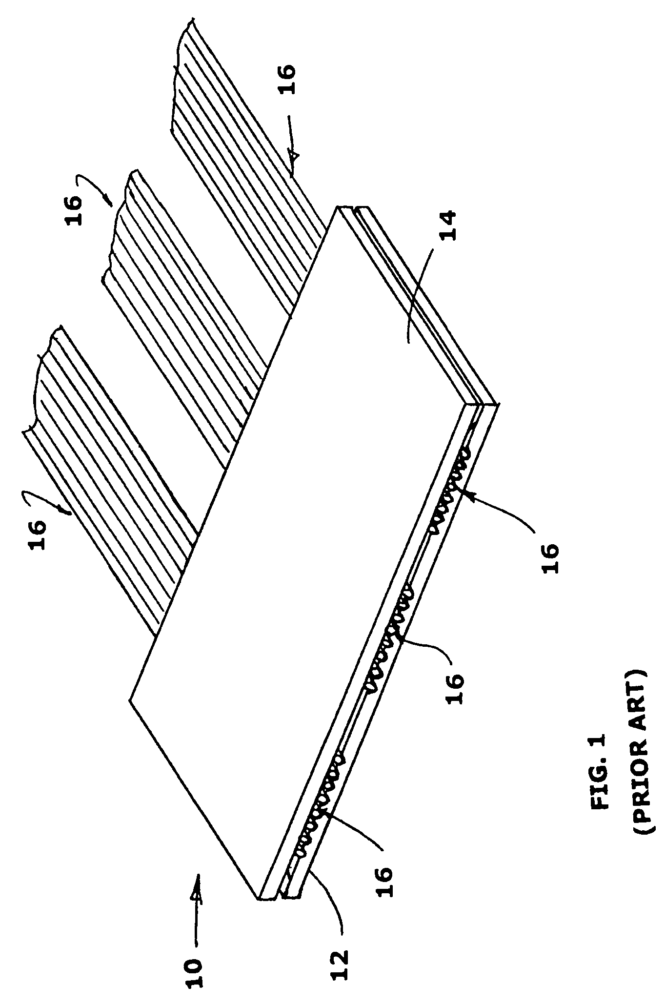
[0019]FIG. 1 shows a typical prior art 16 channel v-groove assembly 10 which includes a substrate 12, a cover plate 14 and three sets or arrays of PM fibres 16 held in the substrate 12. It is noted that in this example the fibres 16 are arranged in three sets or arrays of eight fibres each. Assemblies such as shown in FIG. 1 are available with any number of fibres contained therein, typical assemblies including arrays of 2, 3, 4, 8, 12, 16 . . . or 48 or more fibres. The number of fibres will depend of course on the particular application for which the assembly is to be used.

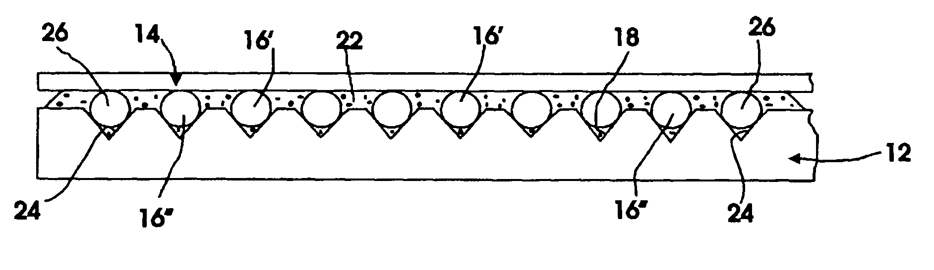
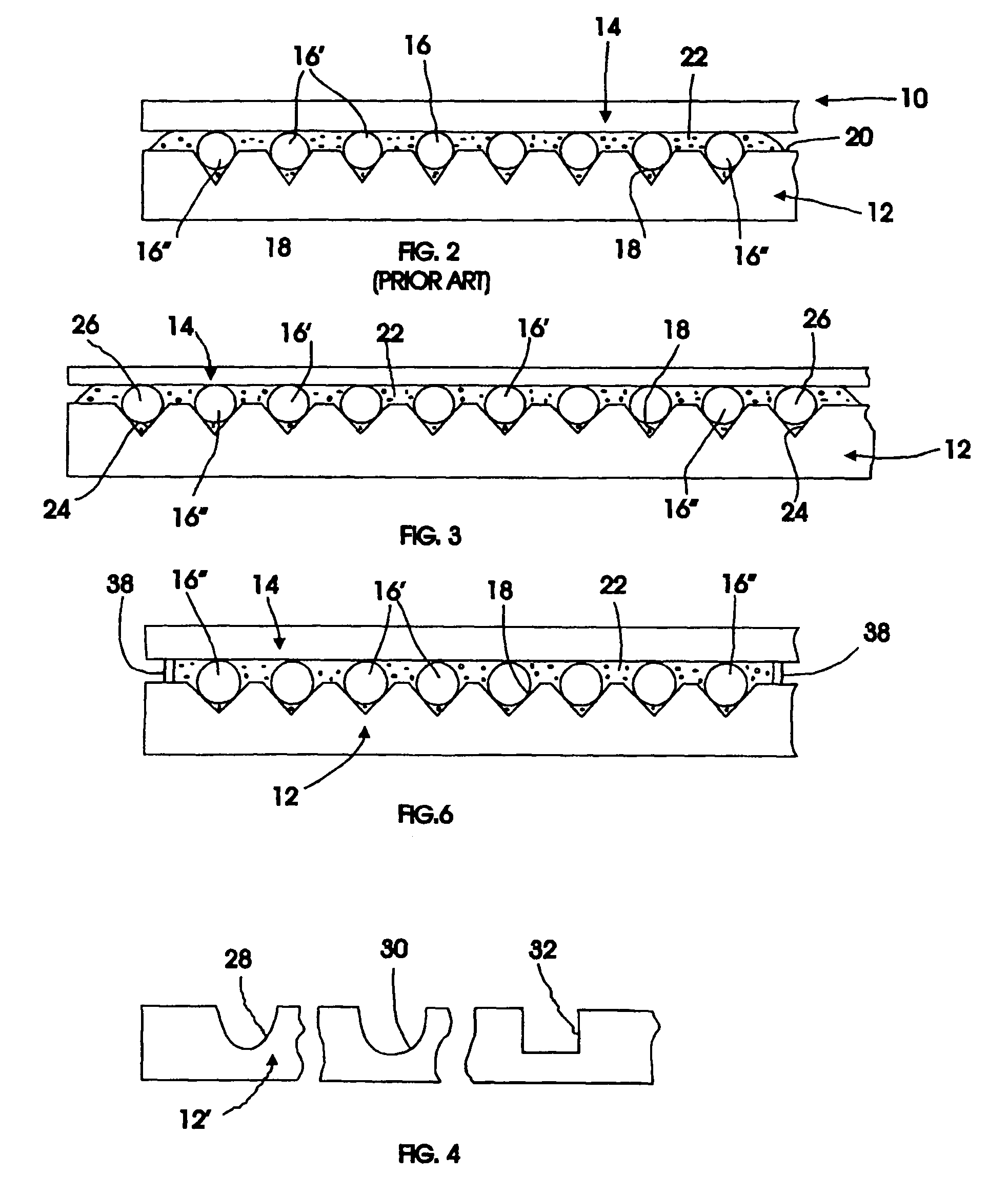
[0020]FIG. 2 shows that the substrate 12 has a plurality of v-shaped grooves 18 therein equally spaced apart across the substrate and opening to the upper surface 20 thereof. In the version shown in FIG. 2 the v-grooves 18 are shown in a set of eight, corresponding to one of the sets or arrays of fibres shown in FIG. 1. It is seen that each groove 18 contains a fibre 16 and that each fibre projects slightly abov...


PUM


Abstract

A mechanism for achieving symmetrical stress loads on operating optical fibers (16) held in fiber optic arrays includes, in one embodiment, the provision of a pair of non-operating or dummy fibers(26), each located outboard of the outermost or curb fibers(16″) of the array. All of the fibers, whether operating or dummy, are held in corresponding grooves (18, 24) in a substrate (12). A cover plate (14) may be positioned thereover while a low stress glue or potting compound (22) is introduced or applied so as to completely encapsulate the fibers. The glue or potting compound will symmetrically surround all of the operating fibers whereby not only any inboard operating fibers (16′), but also the outboard operating curb fibers (16″), are symmetrically encapsulated. In this manner all of the operating fibers are subject to the same stresses and consequently will exhibit essentially the same polarization maintaining behavior. The invention is primarily beneficial with polarization-maintaining optical fibers, but will work effectively with other types of optical fibers as well, wherever stress are a concern.

Description

CROSS REFERENCE TO RELATED APPLICATIONS[0001]This application is a continuation under 35 U.S.C. § 120 and 365(c) of International Application No. PCT / CA2002 / 001268, which was filed on Aug. 16, 2002 and designates the Untied States.BACKGROUND OF THE INVENTION[0002]The present invention relates in general to the relief of asymmetrical stresses in fibre optic arrays, and in particular to the relief of asymmetrical stresses on polarizing (PZ) or polarization-maintaining (PM) fibres supported in grooved assemblies.[0003]Polarization maintaining (PM) fibres are fibres that have been especially developed to maintain polarization of light polarized along one of the principal axes of polarization of the fibre and transmitted therealong under adverse conditions. With such fibres, light polarized along one of the principal axes travels at a different rate than light polarized orthogonal to that axis. In particular, PM fibres will maintain polarization under most stresses applied externally to ...

Claims


Application Information

Patent Timeline
Patent Type & Authority Patents(United States)
IPC IPC(8): G02B6/00G02B6/36G02B6/38
CPCG02B6/3636G02B6/3652G02B6/3855G02B6/3839G02B6/3812
Inventor SEZERMAN, OMURAGHDAM, NASSER Y.NGUYEN, THOBAROCK, H. WAYNE
Owner OZ OPTICS
Why Eureka
Try Eureka