Passive autofocus system for a camera

a camera and autofocus technology, applied in the direction of camera focusing arrangement, printers, instruments, etc., can solve the problems of small focus detection area, long time to determine, and inability to measure the distance of objects with a high degree of accuracy, etc., and achieve the effect of short tim

Active Publication Date: 2006-06-06
RICOH IMAGING COMPANY
View PDF8 Cites 65 Cited by
  • Summary
  • Abstract
  • Description
  • Claims
  • Application Information

AI Technical Summary

Benefits of technology

[0014]According to this structure, the moving range of the focusing lens group by the contrast detecting method is adjusted to decrease as the degree of reliability in the phase-difference in-focus position obtained by the phase-difference detecting method increases. Therefore, it only takes a short time to detect the peak contrast intensity when the degree of reliability is high, while it is possible to detect the peak contrast intensity with reliability even when the degree of reliability is low.
[0021]In another embodiment, an autofocus method is provided, including detecting a position of a focusing lens group, at which a contrast of an object image which passes through a photographing optical system reaches a maximum while moving the focusing lens group; defining the position of the focusing lens group at which the contrast of the object image reaches a maximum as a contrast in-focus position; separating a light bundle of the object image into two light bundles so that the two light bundles are formed as two object images on a light-receiving element to detect a phase difference between the two object images formed thereon; defining a position of the focusing lens group at which an in-focus state is obtained for the object as a phase-difference in-focus position; and commencing a lens driving operation, wherein a distance from the phase-difference in-focus position is controlled in accordance with a degree of reliability of the phase-difference in-focus position.

Problems solved by technology

However, according to the active autofocus method using triangulation, an object distance cannot be measured with a high degree of accuracy.
Moreover, the area on an object on which infrared is projected by the infrared emitter is limited to a small area because a focus detection area is small and because the infrared-projecting direction is fixed, so that there is a tendency for the foreground to be out-of-focus (i.e., the subject is out-of-focus) while the background is in focus.
However, the focus detection area is small and fixed.
However, since the image contrast is detected by moving the focusing lens group in small steps, it takes a long time to determine the peak contrast intensity (in-focus position); moreover, it takes more time to determine the peak contrast intensity if the focusing lens group is positioned far away from an in-focus position thereof.
Specifically, it is known that the aforementioned temporary in-focus position determining operation is performed with a high degree of accuracy for a high-contrast object, and a low degree of accuracy for a low-contrast object, according to each of the phase-difference detecting method and the contrast detecting method, both of which use an image contrast.
Moreover, such conventional focus detecting systems perform a search through an extremely narrow range of focal settings for a low-contrast object, which may cause the peak contrast intensity to be slightly or far out of the searching range to thereby make it impossible to determine the peak contrast intensity.

Method used


Image

  • Passive autofocus system for a camera
  • Passive autofocus system for a camera
  • Passive autofocus system for a camera

Examples


Embodiment Construction

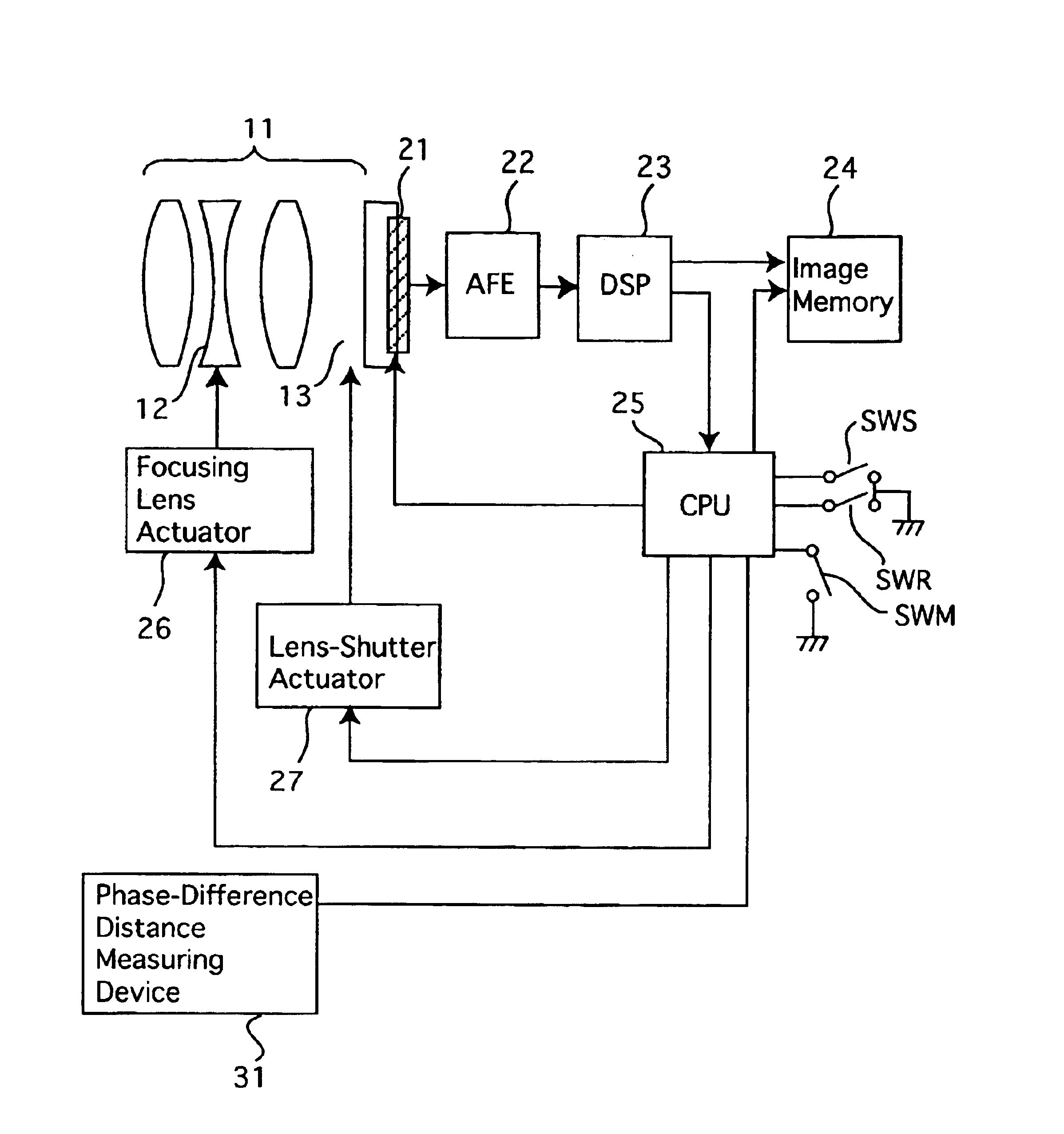
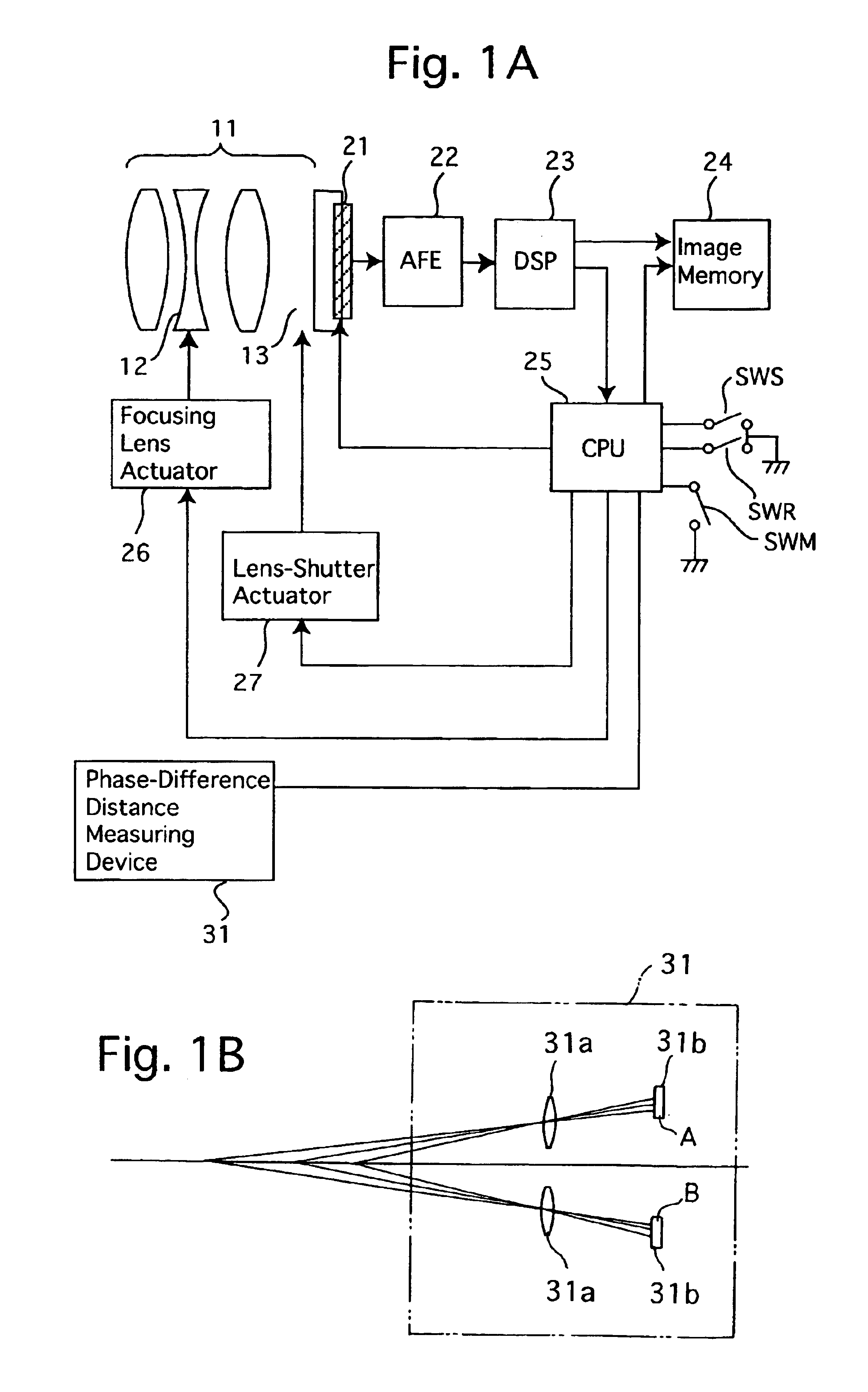
[0039]FIG. 1A shows a schematic circuit diagram of an embodiment of a passive autofocus system for a lens shutter electronic camera according to the present invention. The electronic camera is provided with a photographing lens 11, a CCD image sensor 21, an AFE (analog front end) 22, a DSP (digital signal processor) 23, an image memory 24 and a CPU 25. The CCD image sensor 21, which serves as an image pick-up device, receives a light bundle of an object image which is passed through the photographing lens 11 to convert the incident light of the object image into an electrical picture signal. The AFE 22, which serves as an image processor, processes the picture signal output from the CCD image sensor 21. The electronic camera is provided on a camera body thereof with a release button (not shown), and is further provided with a photometering switch SWS and a release switch SWR which are interconnected with the release button. The photometering switch SWS and the release switch SWR are...


PUM


Abstract

An autofocus system for a camera includes a contrast focus detector which detects a position of a focusing lens group, at which the contrast of an object image reaches a maximum as a contrast in-focus position; a phase-difference focus detector which separates the object image light bundle into two light bundles which form two object images on a light-receiving element to detect a phase difference between the two object images formed thereon, the phase-difference focus detector defining a position of the focusing lens group at which an in-focus state is obtained for the object as a phase-difference in-focus position; and a controller for moving the focusing lens group via the lens driver to the phase-difference in-focus position or the contrast in-focus position. The controller adjusts a moving range of the focusing lens group in accordance with a degree of reliability of the phase-difference in-focus position.

Description

BACKGROUND OF THE INVENTION[0001]1. Field of the Invention[0002]The present invention relates to a passive autofocus system for cameras which use both a passive phase-difference detecting method and a passive contrast detecting method.[0003]2. Description of the Related Art[0004]As conventional focus detecting methods used by autofocus systems for electronic cameras, the active autofocus method using triangulation and the passive autofocus method are known in the art. In addition, a phase-difference detecting method and a contrast detecting method are each known as the passive autofocus method in the art.[0005]The active autofocus method using triangulation uses, e.g., an infrared emitter and a position sensitive detector (PSD) so that an object distance is determined by an application of triangulation, wherein the position sensitive detector receives an infrared signal which is firstly emitted by the infrared emitter and subsequently reflected by an object to be finally incident on...

Claims


Application Information

Patent Timeline
Patent Type & Authority Patents(United States)
IPC IPC(8): G03B13/36G02B7/28G02B7/30G02B7/34G02B7/36H04N5/232
CPCG02B7/285H04N5/23212G02B7/38G02B7/36H04N23/672H04N23/673H04N23/65
Inventor NAKAHARA, NAOTO
Owner RICOH IMAGING COMPANY
Why Eureka
Try Eureka