
Method and apparatus for determining latency between multiple servers and a client

a technology of latency and multiple servers, applied in the field of routing requests, can solve the problems of difficult hop count, critical information management, ip hops, etc., and achieve the effect of reducing network traffi

Inactive Publication Date: 2006-06-06
AKAMAI TECH INC
View PDF35 Cites 445 Cited by
  • Summary
  • Abstract
  • Description
  • Claims
  • Application Information

AI Technical Summary

Benefits of technology

[0014]The invention provides a method and apparatus for determining latency between multiple servers and a client. The system provides a more precise method of determining dynamic hop counts and optimal content servers. In addition, the invention reduces network traffic required for measuring the dynamic hop counts.

Problems solved by technology

The proliferation of information and immense user population has made the management of information critical.
Determining the dynamic hop count is currently problematic due to the following reasons:1. BGP hops: The actual number of hops will typically be larger than that advertised by the BGP protocol since BGP only gives the hops between the ASNs.2. IP hops: Getting hop counts from the Internet Protocol (IP) is difficult because the Time To Live (TTL) field that is part of the IP header is not initialized to standard values by the various TCP / IP stack software running on various Operating Systems, e.g., Windows 98, Linux, NT, etc.

Method used


Image

  • Method and apparatus for determining latency between multiple servers and a client
  • Method and apparatus for determining latency between multiple servers and a client
  • Method and apparatus for determining latency between multiple servers and a client

Examples


Embodiment Construction

[0026]The invention is embodied in a method and apparatus for determining latency between multiple servers and a client in a computer environment. A system according to the invention provides a more precise method of determining dynamic hop counts and optimal content servers. In addition, the invention provides a system that reduces network traffic required for measuring the dynamic hop counts.

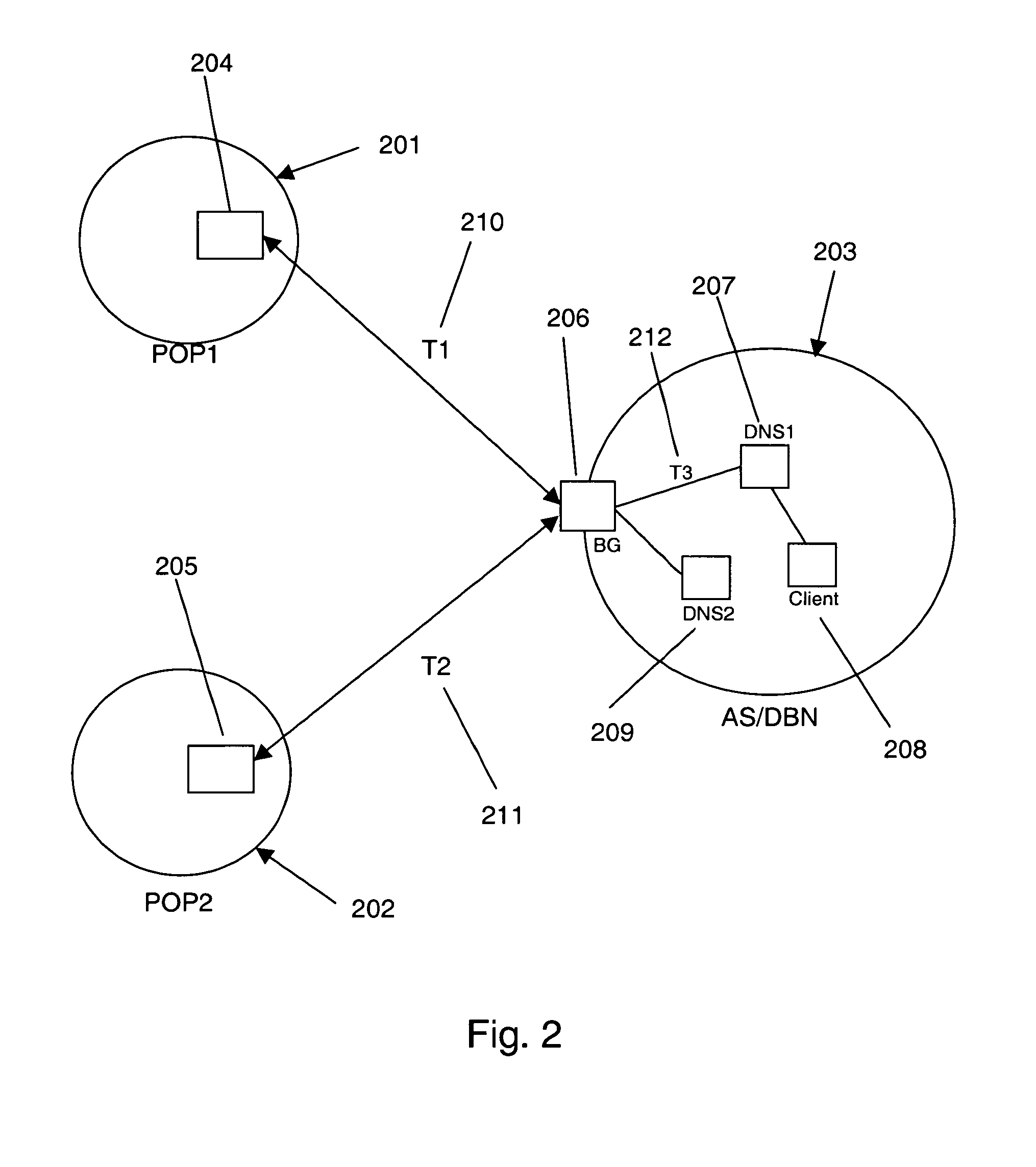
[0027]The invention provides a new method to determine the dynamic hop count between two nodes (client and server). This new method provides a dynamic hop count that is more precise than the hop count obtained using the Border Gateway Protocol (BGP).

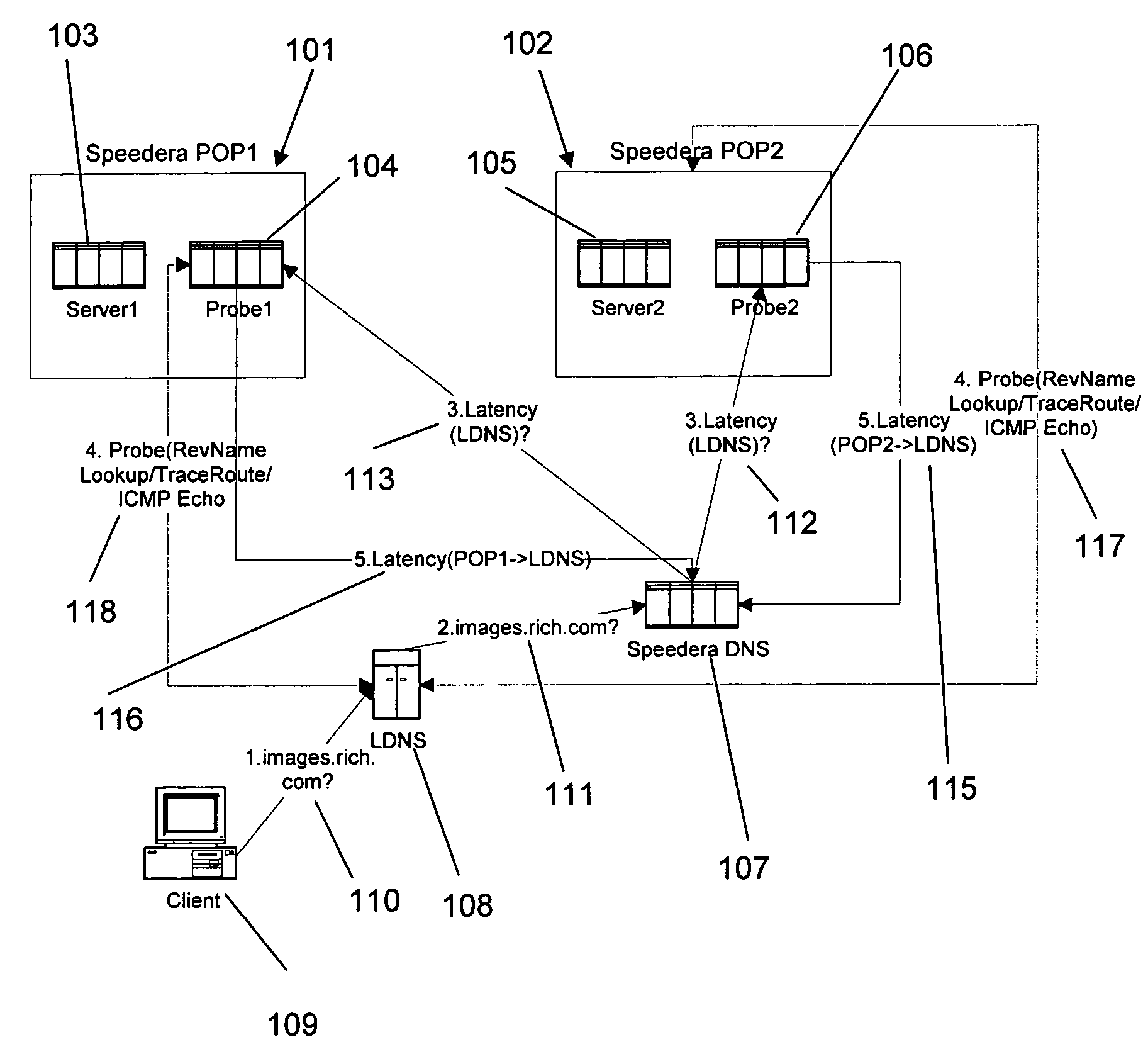
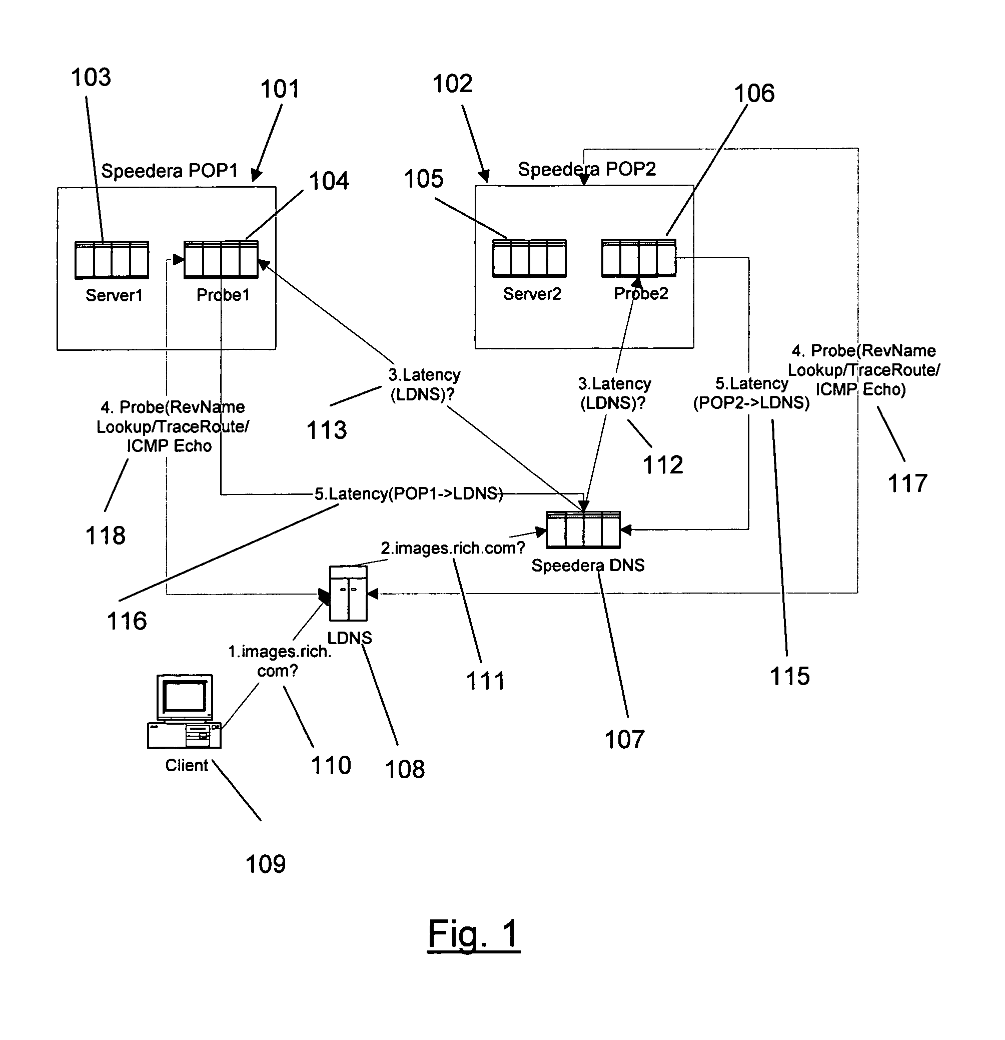
[0028]The latency probes in a Speedera Network are responsible for determining the latency between the Speedera servers and a client. This latency information is used by the Speedera Domain Name Server (SPDNS) to direct a client to the server that is “closest” to the client in latency.

[0029]Referring to FIG. 1, each Speedera Point of Presence (POP)...


PUM


Abstract

A method and apparatus for determining latency between multiple servers and a client receives requests for content server addresses from local domain names servers (LDNS). POPs that can serve the content are determined and sent latency metric requests. The content server receives the request for latency metrics and looks up the latency metric for the requesting client. Periodic latency probes are sent to the IP addresses in a Latency Management Table. The IP addresses of clients are masked so the latency probes are sent to higher level servers to reduce traffic across the network. The hop count and latency data in the packets sent in response to the latency probes are stored in the Latency Management Table and is used to determine the latency metric from the resident POP to the requesting client before sending the latency metric to the requesting server. The BGP hop count in the Latency Management Table is used for the latency metric upon the first request for an IP address. The latency metric is calculated for subsequent requests of IP addresses using the hop count and RTT data in the Latency Management Table. Latency metrics from POPs are collected and the inverse relationship of the hop counts in a weighted combination with the RTT are used to determine which latency metric indicates the optimal POP. The address of the optimal POP is then sent to the requesting LDNS.

Description

CROSS-REFERENCES TO RELATED APPLICATIONS[0001]The present application claims priority to U.S. Provisional Application No. 60 / 193,988 filed Mar. 31, 2000 commonly owned, and hereby incorporated by reference for all purposes.BACKGROUND OF THE INVENTION[0002]1. Technical Field[0003]The invention relates to the routing of requests to a networked server in a computer environment. More particularly, the invention relates to determining a dynamic hop count between two nodes across a network in a computer environment.[0004]2. Description of the Prior Art[0005]The Internet is a confederation of loosely connected networks that connect computers all around the world. The proliferation of information and immense user population has made the management of information critical. Information is mirrored on multiple servers in order to improve performance, availability, and scalability.[0006]To facilitate the mirroring of information, clients requesting information need to be routed to the optimal s...

Claims


Application Information

Patent Timeline
IPC IPC(8): G06F15/173H04L12/24H04L12/56H04L29/06H04L29/12
CPCH04L43/0852H04L45/12H04L69/161H04L69/16H04L45/121H04L29/12047H04L29/12783H04L61/15H04L61/35H04L61/45
Inventor IYER, SHANKARLANKA, SRIDHARA
Owner AKAMAI TECH INC
Learn More