Distributed program relocation for a computer system

a computer system and program technology, applied in the field of computer software, can solve the problems of limited data that can be stored on the embedded system, lack of storage capability, and inability to meet the needs of cleaning, etc., and achieve the effect of/or reducing the number of embedded systems

Inactive Publication Date: 2006-06-06
MATSUSHITA ELECTRIC WORKS LTD
View PDF12 Cites 13 Cited by
  • Summary
  • Abstract
  • Description
  • Claims
  • Application Information

AI Technical Summary

Benefits of technology

[0019]The presently preferred embodiments use a minimal set of software routines for accessing storage on an embedded device (EEPROM, FLASH, battery backed-up RAM, etc.), while providing a substantial portion of the higher-level (and larger) memory-management software components on a computer connected to the embedded device(s). Thus, the preferred embodiments allow an embedded device, its capabilities and / or its features to be upgraded or enhanced.

Problems solved by technology

For example, the computer software running on a processor in a vending machine may cause a soda pop to drop to a user when the correct change has been entered by a user.
Typically the embedded systems used today with various appliances, devices, etc., do not have a lot of storage capability.
As a result, the amount of data that can be stored on the embedded systems is limited.
With only limited storage, an embedded system may not have as many features and capabilities as it could have if it had more available storage.
However, in many embedded devices, these types of memory management capabilities are not available.
In these types of environments, any program code is typically developed and loaded onto the embedded device by the manufacture before the device is shipped, after which software upgrades are rarely if ever even contemplated.
Because many embedded devices do not have extensive memory management capabilities, it is often difficult to easily upgrade the software, upgrade modules, upgrade components and / or to add new software, new components, new modules, new features, new extensions, etc.

Method used


Image

  • Distributed program relocation for a computer system
  • Distributed program relocation for a computer system
  • Distributed program relocation for a computer system

Examples


Embodiment Construction

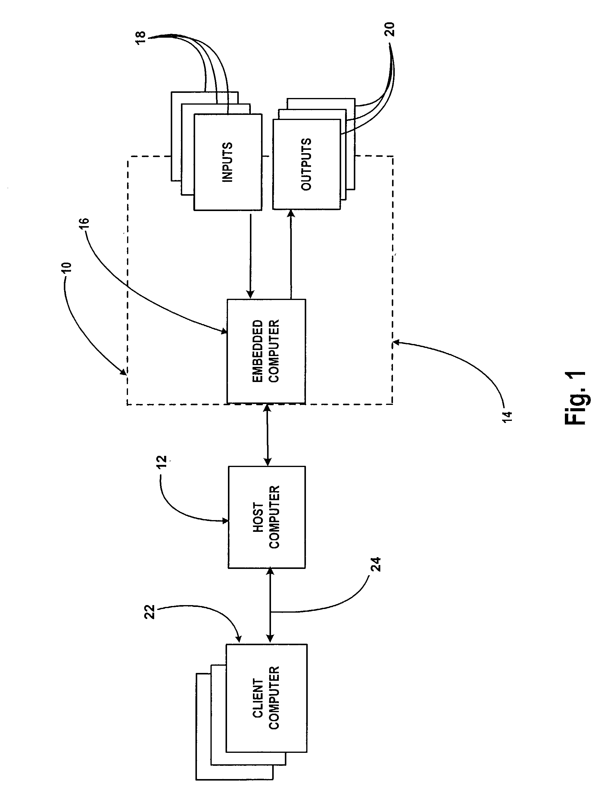
[0026]It will be readily understood that the components of the embodiments, as generally described and illustrated in the Figures herein, could be arranged and designed in a wide variety of different configurations. Thus, the following more detailed description of the embodiments of the systems and methods disclosed, as represented in FIGS. 1 through 5, is not intended to limit the scope of the invention, as claimed, but is merely representative of the presently preferred embodiments.

[0027]The presently preferred embodiments will be best understood by reference to the drawings, wherein like parts are designated by like numerals throughout.

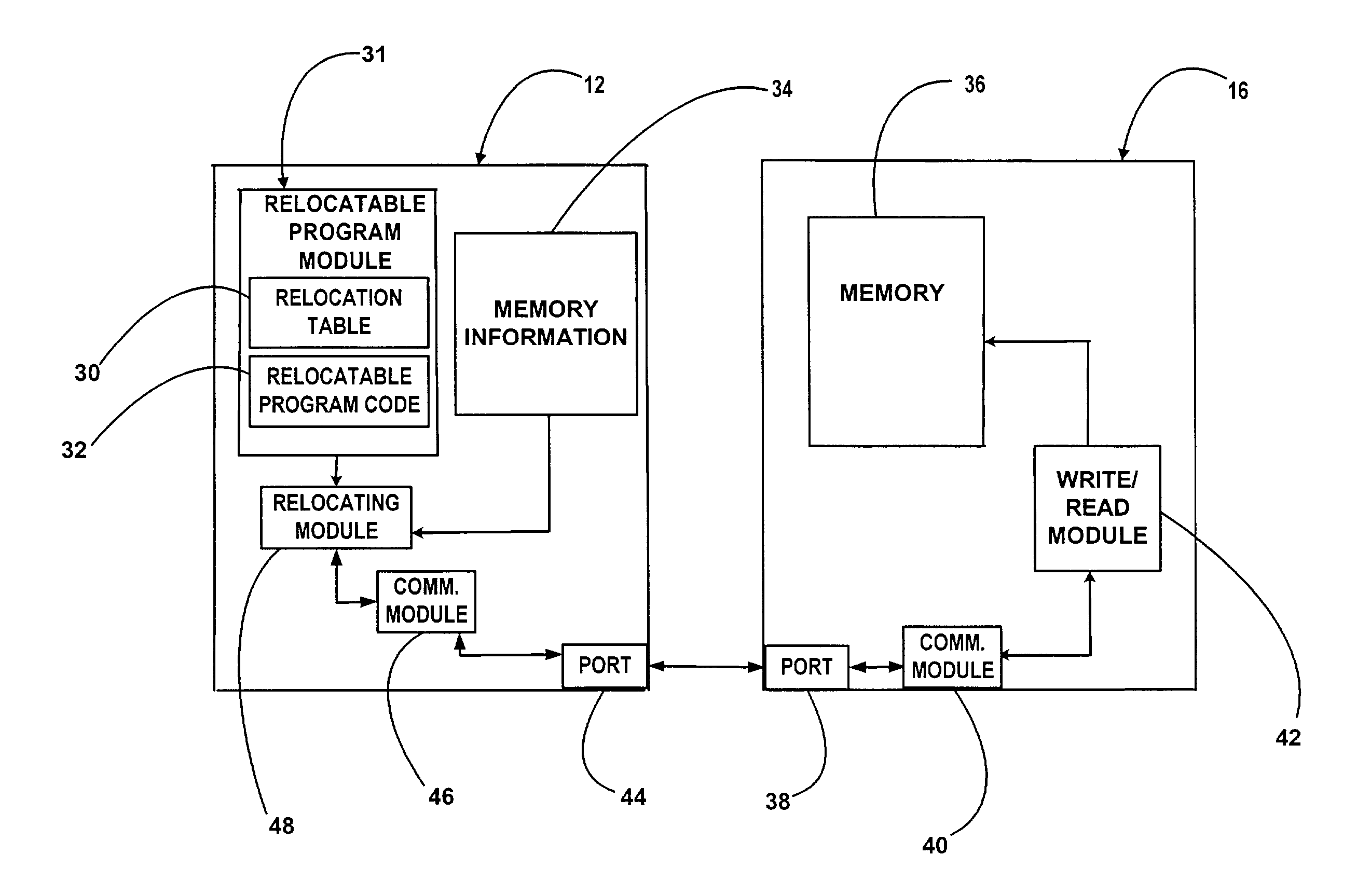
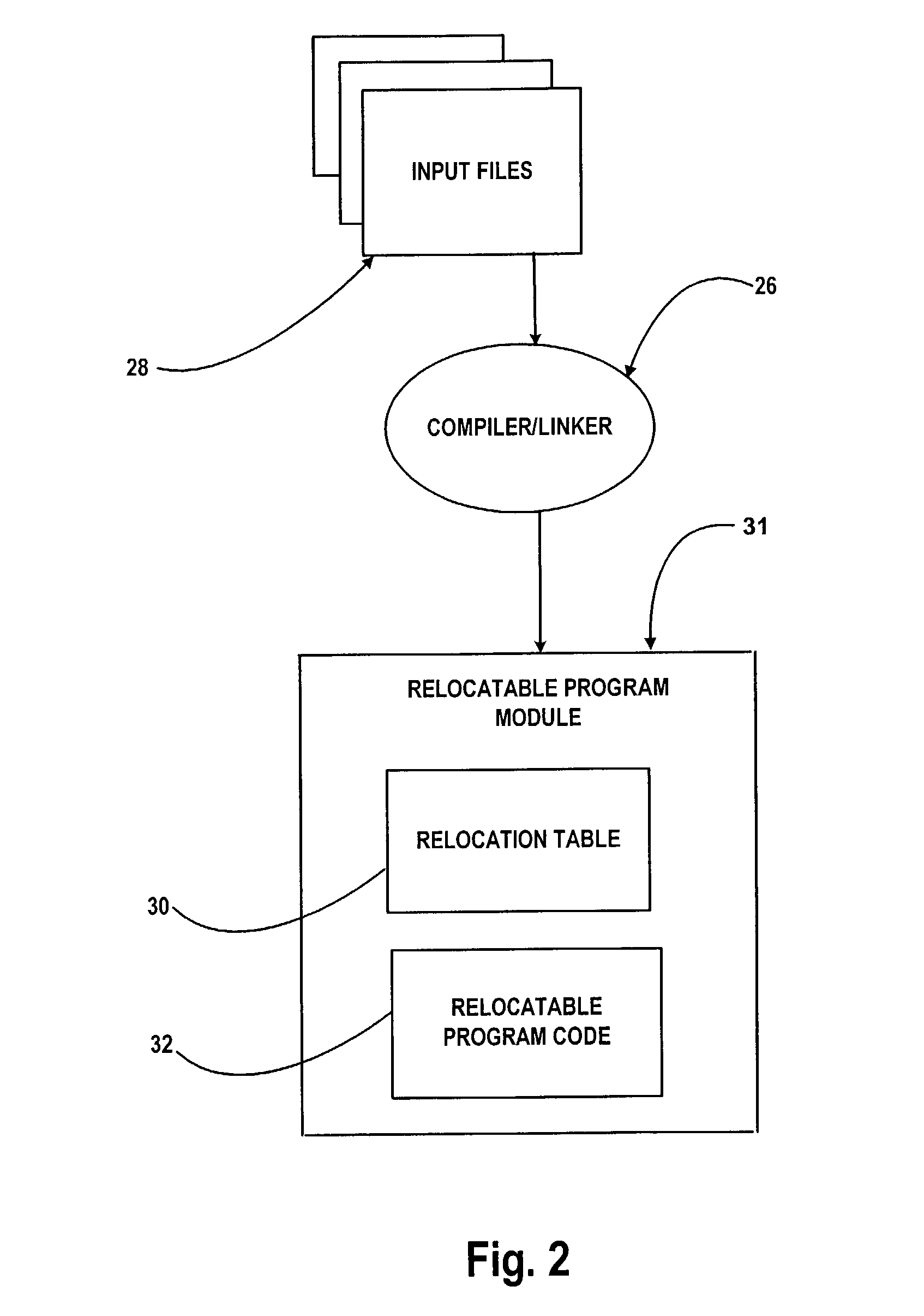
[0028]A system for preparing program code for a first computer, wherein the system is implemented on a second computer, includes a relocating module that is adapted to relocate program code by modifying locations in the program code identified by location data. The modifications made by the relocating module are based on a memory address. The syste...


PUM


Abstract

Systems and methods are disclosed for preparing program code for a first computer, wherein the systems and methods are implemented on a second computer. The systems include a relocating module that is adapted to relocate program code by modifying locations in the program code identified by location data. The modifications made by the relocating module are based on a memory address. The systems operate on program code for the first computer, where the program code is stored on the second computer. The relocating module is provided the memory address that identifies a memory location in the first computer. The memory address is suitable as a basis for modifying the program code. The relocating module is also provided with location data that identifies locations in the program code to be adjusted based on the memory address.

Description

[0001]This application is a continuation of U.S. patent Ser. No. 09 / 465,475 filed Dec. 16, 1999, now U.S. Pat. No. 6,467,084.BACKGROUND[0002]1. The Field of the Invention[0003]This invention relates to computer software and, more particularly, to novel systems and methods for distributing and relocating computer software and data across a computer network.[0004]2. The Background Art[0005]In recent years there has been a great increase in the amount of computer technology that is involved in daily life. In today's world, computer technology is involved in many aspects of a person's day. Many devices being used today by consumers have a small computer inside of the device. These small computers come in varying sizes and degrees of sophistication. These small computers include everything from one microcontroller to a fully-functional complete computer system. For example, these small computers may be a one-chip computer, such as a microcontroller, a one-board type of computer, such as ...

Claims


Application Information

Patent Timeline
Patent Type & Authority Patents(United States)
IPC IPC(8): G06F9/45B08B9/093A47L15/00B05B1/14B08B3/02B08B9/28G06F9/445
CPCG06F8/54
Inventor HOWARD, MICHAEL L.COFFIN, STEPHEN C.
Owner MATSUSHITA ELECTRIC WORKS LTD
Why Eureka
Try Eureka