Hydrodynamic type porous oil-impregnated bearing

a technology of porous oil and bearings, which is applied in the direction of bearings, shafts and bearings, rotary bearings, etc., can solve the problems of accelerating oxidative deterioration of oil, affecting the bearing life, so as to improve the effect of lubricating oil film formation, the effect of reducing the deterioration of oil

Inactive Publication Date: 2006-06-13
NTN CORP
View PDF57 Cites 30 Cited by
  • Summary
  • Abstract
  • Description
  • Claims
  • Application Information

AI Technical Summary

Benefits of technology

[0007]An object of the present invention is to secure the appropriate circulation of oil between the interior of the bearing body and the bearing clearance to suppress the deterioration of the oil in the bearing clearance, thereby increasing the bearing life, and improving the effect of formation of lubricating oil film in the bearing clearance, thus increasing the bearing rigidity and minimizing the shaft deflection due to imbalance load or the like.
[0008]Another object of the invention is to provide an arrangement which is capable of preventing unstable vibrations such as whirl and eliminating the inconveniences (such as the loss of shape of hydrodynamic pressure generating grooves, and axial misalignment) which are involved in the installing operation.
[0009]A further object of the invention is to provide a production method which facilitates the forming of a bearing surface having inclined hydrodynamic pressure generating grooves by using simple equipment and fewer steps and with high accuracy.

Problems solved by technology

However, since a porous oil-impregnated bearing is a kind of cylindrical bearing, it tends to produce unstable vibrations where the shaft eccentricity is small, inducing the so-called whirl in which the shaft is subjected to a revolving vibration at a rate which is half the rotary speed.
Such construction, however, has the following drawback.
Since the surface openings on the region of the hydrodynamic pressure generating grooves completely sealed, the circulation of oil, which is the greatest feature of the porous oil-impregnated bearing, is obstructed.
A great shearing action is present in the bearing clearance, and this shearing force and frictional heat cause the oil staying in the groove region to be denatured, while a rise in temperature tends to accelerate oxidative deterioration of the oil.
On the other hand, besides plastic processing, it has been proposed to employ coating or the like as another means for applying a surface treatment, however, it is necessary that the thickness of such coating film be less than the grooves depth, and it is very difficult to apply a coating film which is some μm thick solely to the groove region.
In the case of a bearing having hydrodynamic pressure generating grooves formed in the bearing surface, if forcible correction is made by using the correction pin, this will result in the correction pin cutting into the hydrodynamic pressure generating grooves in the bearing surface to collapse said grooves, making it impossible to obtain a stabilized hydrodynamic effect.
On the other hand, the operation of press-fitting without using the correction pin will fail to provide the necessary alignment between the bearings.
This arrangement, though free from the aforesaid problems in practice, cannot prevent the unstable vibrations, such as whirl, because of the lack of hydrodynamic pressure generating grooves in the bearing surfaces.
Further, a driving mechanism and an advancing mechanism for the jig are required, thus complicating the manufacturing equipment.

Method used


Image

  • Hydrodynamic type porous oil-impregnated bearing
  • Hydrodynamic type porous oil-impregnated bearing
  • Hydrodynamic type porous oil-impregnated bearing

Examples


Embodiment Construction

[0043]Embodiments of the present invention will now be described.

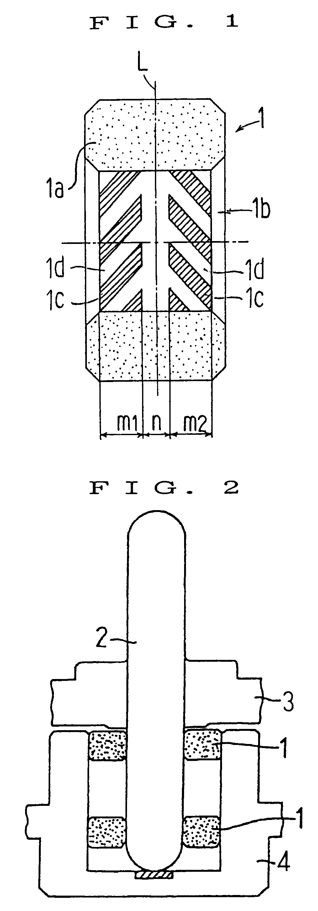
[0044]FIG. 1 shows by way of example an embodiment of a hydrodynamic type porous oil-impregnated bearing. This hydrodynamic type porous oil-impregnated bearing 1 is used, for example, in connection with a scanner motor for a laser beam printer shown in FIG. 2, to support a spindle shaft 2 for rotation with respect to a housing 4, in a non-contact manner, the spindle shaft 2 being rotated at high speed by magnetic excitation force between a rotor 3 and a stator.

[0045]The porous oil-impregnated bearing 1 comprises a bearing body 1a made of a porous material, e.g., a sintered metal containing copper or iron, or both as a main component, and oil retained in the pores of the bearing body 1a by impregnation with lubricating oil or lubricating grease. The bearing body preferably contains copper in 20–95 wt %, and has density of 6.4–7.2 g / cm3.

[0046]The inner peripheral surface of the bearing body 1a is formed with a bearing su...


PUM

PropertyMeasurementUnit
melting pointaaaaaaaaaa
temperatureaaaaaaaaaa
sizeaaaaaaaaaa

Abstract

The porous oil-impregnated bearing 1 comprises a bearing body 1a made of a porous material, and oil retained in the pores of the bearing body 1a by impregnation with lubricating oil or lubricating grease. The inner peripheral surface of the bearing body 1a is formed with a bearing surface 1b opposed to an outer peripheral surface of a shaft to be supported, with a bearing clearance defined therebetween. The bearing surface 1b has a first region m1 in which a plurality of hydrodynamic pressure generating grooves 1c inclined in one direction with respect to the axial direction are circumferentially disposed, a second region m2 which is axially spaced from said first region m1 and in which a plurality of hydrodynamic pressure generating grooves 1c inclined in the other direction with respect to the axial direction are circumferentially disposed, and an annular smooth region n disposed between the first and second regions m1 and m2.

Description

[0001]This is a Division of Application Ser. No. 09 / 033,651 filed Mar. 3, 1998, now U.S. Pat. No. 6,299,356. The disclosure of the prior application is hereby incorporated by reference herein in its entirety.BACKGROUND OF THE INVENTION[0002]The present invention relates to a hydrodynamic type porous oil-impregnated bearing being impregnated with lubricating oil or lubricating grease in a bearing body of porous substance, such as sintered metal, to have a self-lubricating function, supporting a slide surface of a shaft in a non-contact manner by a lubricating oil film produced in a bearing clearance due to hydrodynamic function of hydrodynamic pressure generating grooves in a bearing surface. The bearing of the invention is suitable for use particularly in machines and instruments of which high rotation accuracy at high speed is required, such as spindle motors for polygon mirror of laser beam printer (LBP), magnetic disk drives (HDDs), or the like, and in machines and instruments wh...

Claims


Application Information

Patent Timeline
Patent Type & Authority Patents(United States)
IPC IPC(8): B21K1/10F16C33/10
CPCF16C17/026F16C17/107F16C33/107F16C33/145F16C33/104Y10T29/49639F16C17/02F16C33/106
Inventor OKAMURA, KAZUOYAMAMOTO, YASUHIROKOMORI, ISAOMORI, NATSUHIKOSHIRANAMI, MAKOTO
Owner NTN CORP
Why Eureka
Try Eureka