

Valve mechanism for tube-type fluid container
a valve mechanism and fluid container technology, applied in the field of valve mechanisms, can solve the problems of high manufacturing cost of the valve mechanism using the spherical valve body and the spring, and achieve the effect of reliably closing the fluid
- Summary
- Abstract
- Description
- Claims
- Application Information
AI Technical Summary
Benefits of technology
Problems solved by technology
Method used
Image

Examples
embodiment 1
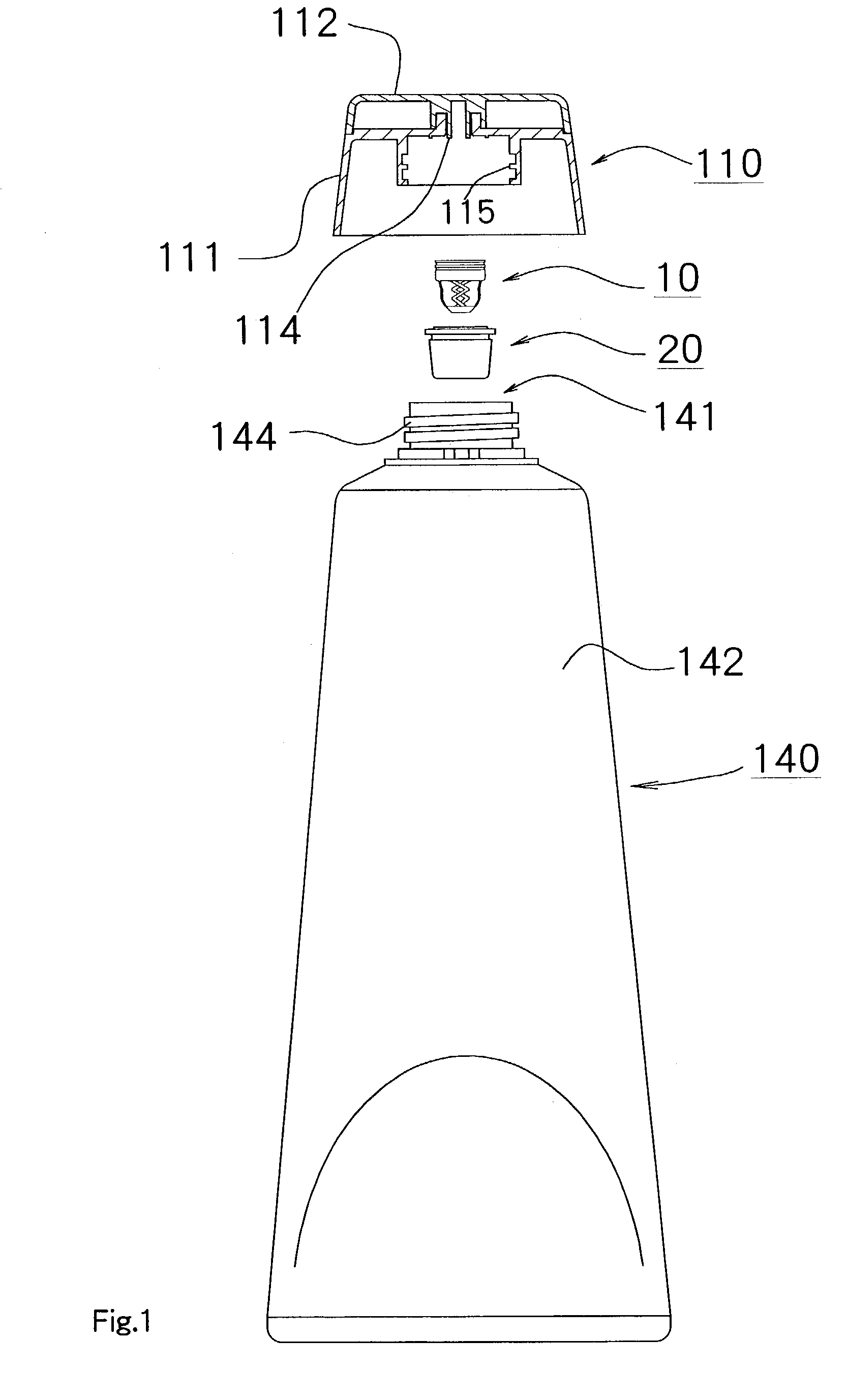
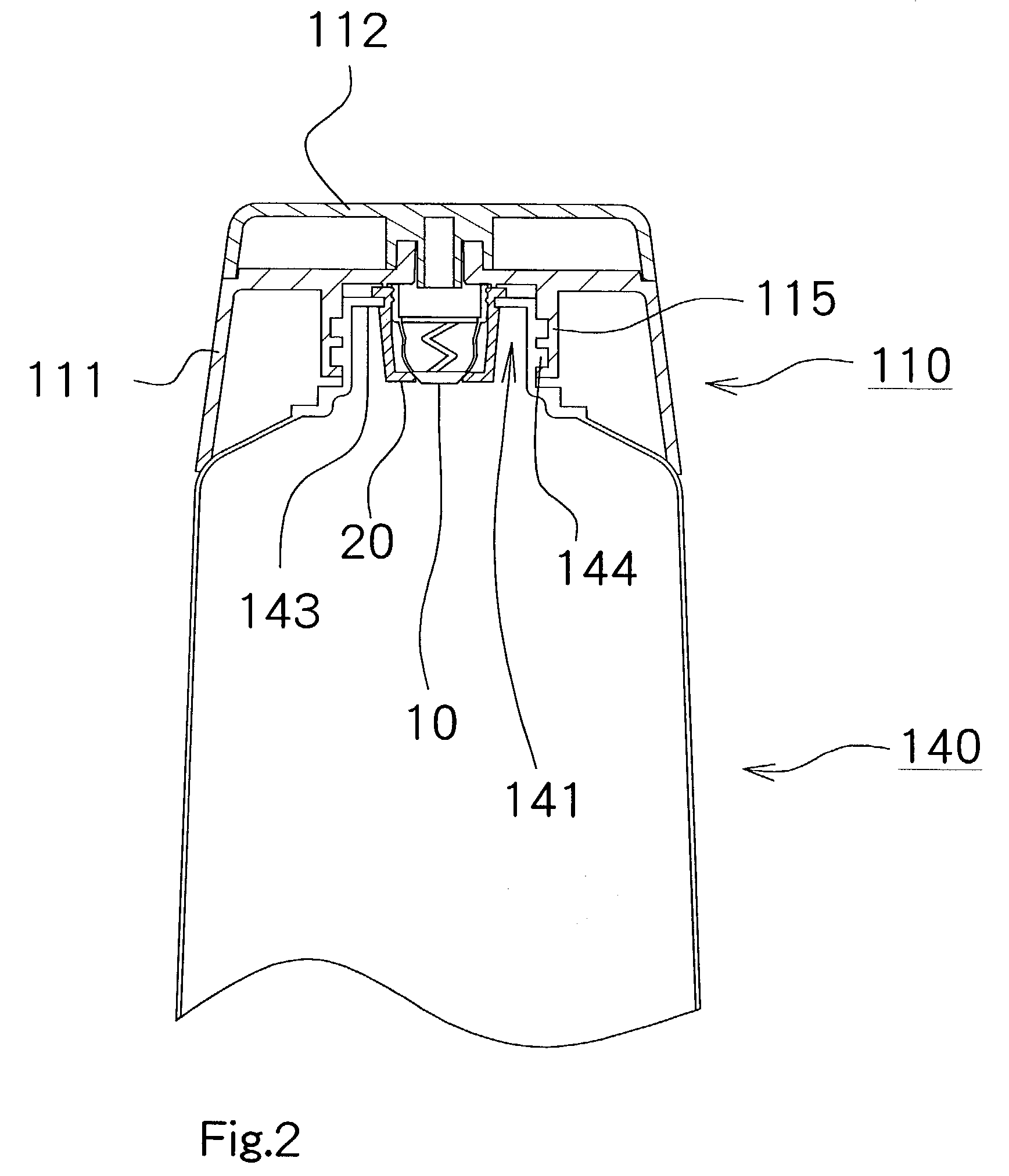
[0072]A configuration of the valve mechanism according to the present invention is described below. FIGS. 5A and 5B are illustrations showing the valve portion 10 and the valve seat portion 20, which comprise the valve mechanism of the present invention. FIGS. 6A and 6B are sectional views showing the motion of the valve mechanism. Additionally, FIG. 5A shows a plan view of the valve portion 10; FIG. 5B shows a view that the valve portion 10 and the valve seat portion 20 are assembled. In FIG. 5B, a lateral view of the valve portion 10 and a sectional view of the valve seat portion 20 are shown.
[0073]As shown by these views, the valve seat portion 20 has a nearly tubular shape, at the bottom of which a circular opening portion 23 functioning as a valve seat is formed. Upward inside this valve seat portion 20, a pair of protruding portions 24 are formed.
[0074]The valve portion 10 has a ring-shaped supporting portion 11 which is arranged inside the valve portion 20, a valve body 12 h...
embodiment 2
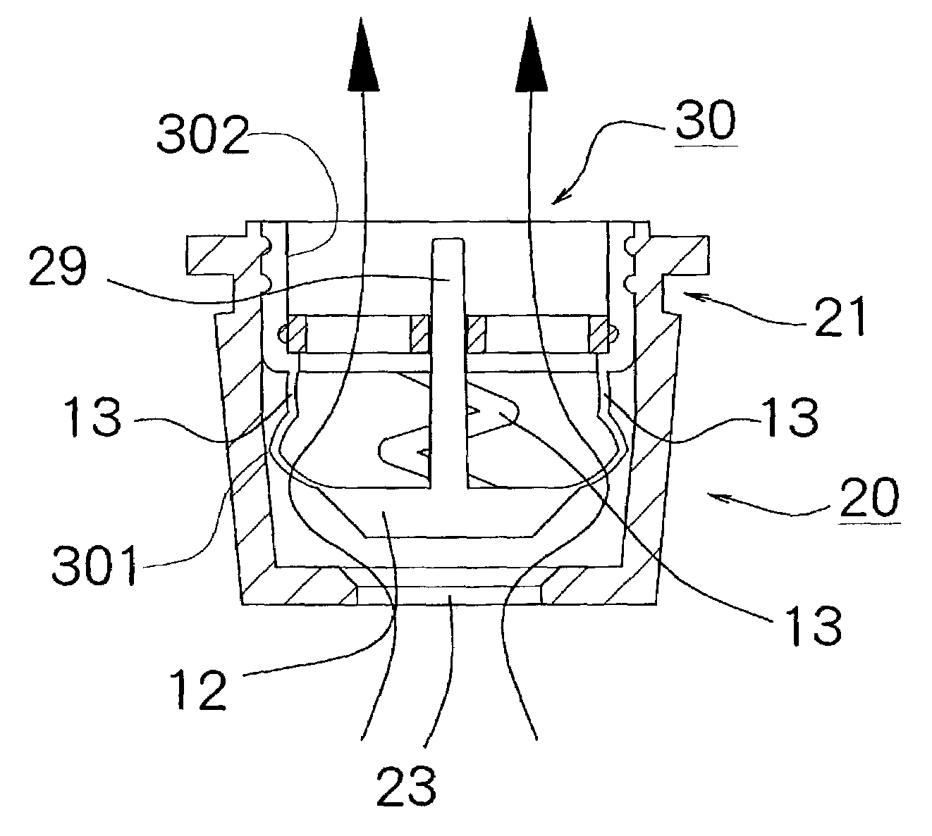
[0085]In other words, in the valve mechanism , a guide pin 29 is set up by standing it on the top of the valve body 12 in the valve portion 30. A guide material 16 is set up at an inner position of a supporting portion 11 in the valve portion 30. The guide material 16 comprises a ring-shaped supporting portion 17, three coupling portions 18 and a hole portion for guiding 19, which encircles the guide pin 29 from its circumferential portion.
[0086]In the valve mechanism according to Embodiment 2, when the valve body 12 moves from the closed position to the open position, occurrence of an inadequate tilt of the valve body 12 is able to be prevented because the guide pin 29, which is provided by standing it in the valve body 12, is guided by the guiding hole portion 19 of the guiding material 16. Additionally, as in this Embodiment 2, when the guide mechanism which guides a movement of the valve body 12 from its closed position to its open position is provided, the number of the couplin...
embodiment 3
[0089]The valve seat portion 20 of the valve mechanism has a valve seat portion having a nearly tubular shape, at the bottom of which a circular opening portion 26 which functions as a valve seat is formed. Upward inside this valve seat portion 20, a concave portion 25 is formed.
[0090]The valve portion 40 has a ring-shaped supporting portion 41 provided inside the valve seat portion 20, a valve body 42 having a shape corresponding to the circular opening portion 26 in the valve portion 20, and four coupling portions 43, which couple the supporting portion 41 and the valve body 42. The four coupling portions 43 have a pair of flections 44 respectively. In this valve portion 40, the valve body 42 is constructed in such a way that the valve body 42 can move between a closed position in which the valve body closes the opening portion 26 in the valve seat portion 20 and an open position in which the valve body opens the opening portion 26 by the flexibility of the four coupling portions...
PUM
 Abstract
Description
Claims
Application Information