
Thread supplying device

a technology of supplying device and thread, which is applied in the direction of weaving, transportation and packaging, looms, etc., to achieve the effect of easy integration, simple control, and fair manufacturing cos

Inactive Publication Date: 2006-06-13
IROPA AG (CH)
View PDF12 Cites 0 Cited by
  • Summary
  • Abstract
  • Description
  • Claims
  • Application Information

AI Technical Summary

Benefits of technology

[0005]Equipping the thread supplying device with the permanent magnet motor results in the advantage that fewer compromises have to be accepted in view to the operational performance than in case of an asynchronous motor. The permanent magnet motor can be controlled more simply, is compact and can be manufactured for fair costs in series production. The permanent magnet motor has overall the important advantage that it easily can be integrated into computerised data transmission systems and signal transmission systems, respectively, of textile machines. The unavoidable effect of several stable and instable rotational positions of the rotor without current supply due to the design of the permanent magnet motor intentionally is used to retain the thread guiding element in the threading position relatively stably, because the co-operating component group consisting of the stator, the rotor of the permanent magnet motor, the motor shaft and the thread guiding element are mounted in the housing such that one of the stable relative rotational positions of the rotor is the target rotational position of the motor shaft and, consequently, the threading position of the thread guiding element. By this structural measure it is possible to position the thread guiding element during the stop phase of the permanent magnet motor correctly in the threading position and to safely retain it in the threading position without additional means. When preparing the concept of the thread supplying device under consideration of the stable and instable relative rotational positions of the rotor it is necessary to exclude random motor mounting positions but to ensure a predetermined motor mounting position when assembling and designing the thread supply device.

Problems solved by technology

The phenomenon of the permanent magnet motor results in problems in a thread supplying device being equipped with a threading means when the motor shaft has to stop in a determined target position in which the thread guiding element is intended to co-act with the threading means.

Method used


Image

  • Thread supplying device
  • Thread supplying device
  • Thread supplying device

Examples


Embodiment Construction

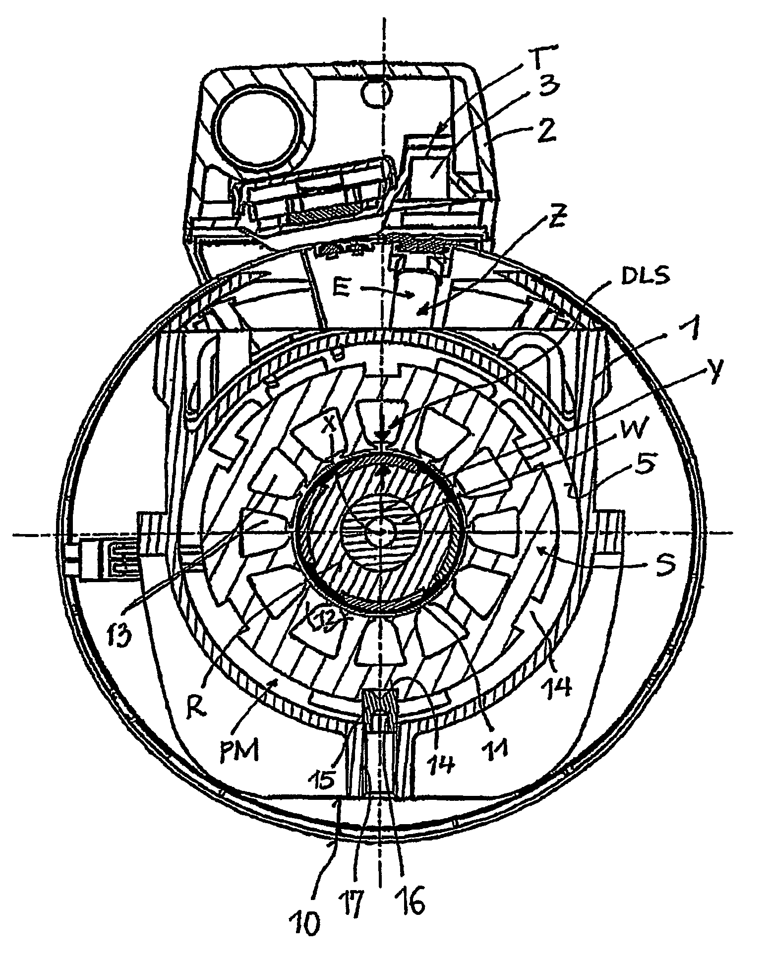
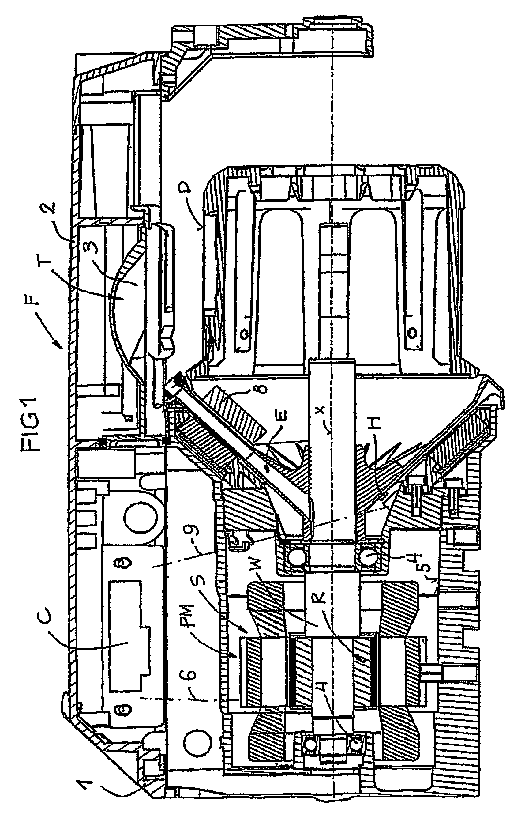
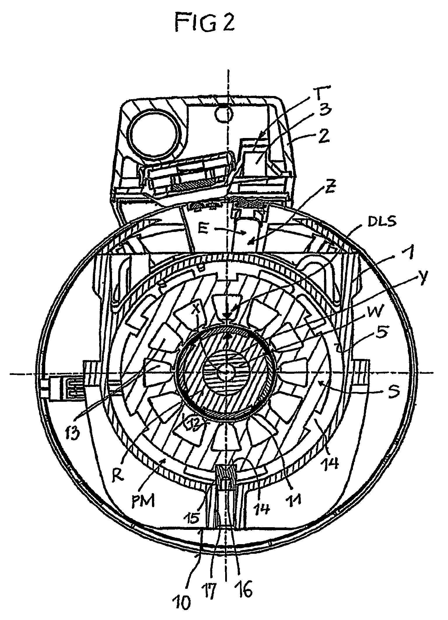
[0017]A thread supplying device F as shown in FIGS. 1 and 2 is a weft thread supplying device for a weaving machine. The thread supplying device F has an equipment allowing to manually or automatically or semi-automatically thread in a new thread.

[0018]The thread supplying device F has a massive housing 1 and a housing bracket 2. In the lower side of the bracket 2 a guide track 3 is provided constituting a threading means T. The guide track 3 serves either for guiding a threading needle or an air stream conveying a new thread through the thread supplying device F, respectively.

[0019]In a cavity 5 of the housing 1 a permanent magnet motor PM is mounted serving as the drive of a thread guiding element E. The thread guiding element E transports a not shown thread coming from the left side through the thread guiding element E to a storage surface of a storage body D in order to form a not shown thread supply. For consumption, the thread in FIG. 1 is withdrawn to the right side.

[0020]The...


PUM


Abstract

A thread supplying device provided with a housing containing an electric motor wherein the stator is non-rotatingly mounted and the rotor is rotatingly mounted on a motor shaft. A thread guiding element is fixed to the motor shaft and a threader device which is fixed to the housing is also provided. When the motor shaft is in a set rotational position, the thread guiding element is physically associated with said threader device. A permanent magnet motor with pole cores provided with windings is integrated into the stator and permanent magnets are integrated into the rotor in such a way that the stator, rotor and the thread guiding element are arranged relative to the housing, in such a way that the motor shaft adopts the set position of rotation when the permanent magnet motor is devoid of electric current in a stable relative position of rotation, caused by magnetic forces, of the rotor in the stator.

Description

FIELD OF THE INVENTION[0001]The invention relates to a thread supplying device.BACKGROUND OF THE INVENTION[0002]The electric motor of known thread supplying devices is an asynchronous motor needing complicated control electronics due its design and shows an operation performance which needs to accept some compromises when driving the thread guiding element of the thread supplying device. Among known thread supplying devices there are variants differing in equipment for threading of a new thread or even for automatically re-threading. When manually threading a new thread with a threading needle a guiding track provided in a housing bracket may be used for the threading needle in order to bring the new thread towards the withdrawal area. In case of an automatic or semi-automatic pneumatic threading system a guiding track may be provided as the threading means in the housing bracket and for the air stream conveying the new thread. In both cases it is necessary to register the thread gu...

Claims


Application Information

Patent Timeline
Patent Type & Authority Patents(United States)
IPC IPC(8): B65H51/20H02K21/12B65H51/22D03D47/36
CPCD03D47/361B65H51/22
Inventor JOHANSSON, EGONJOSEFSSON, PAER
Owner IROPA AG (CH)
Learn More