
Gas turbine generating apparatus

a technology of generating apparatus and gas turbine, which is applied in the direction of motor/generator/converter stopper, turbine/propulsion engine ignition, dynamo-electric converter control, etc., can solve the problems of large installation space and high initial cost of introducing the generating facility, and achieve the effect of easy interconnection

Inactive Publication Date: 2006-06-13
EBARA CORP +1
View PDF8 Cites 133 Cited by
  • Summary
  • Abstract
  • Description
  • Claims
  • Application Information

AI Technical Summary

Benefits of technology

[0006]The present invention has been made in view of the above circumstances. It is an object of the present invention to provide a gas turbine generating apparatus which can be easily interconnected to a commercial power supply system and can supply alternating-current power at a desired power factor, e.g., a power factor of 1, to the commercial power supply system.
[0007]Another object of the present invention is to provide a gas turbine generating apparatus which can be started easily and quickly.
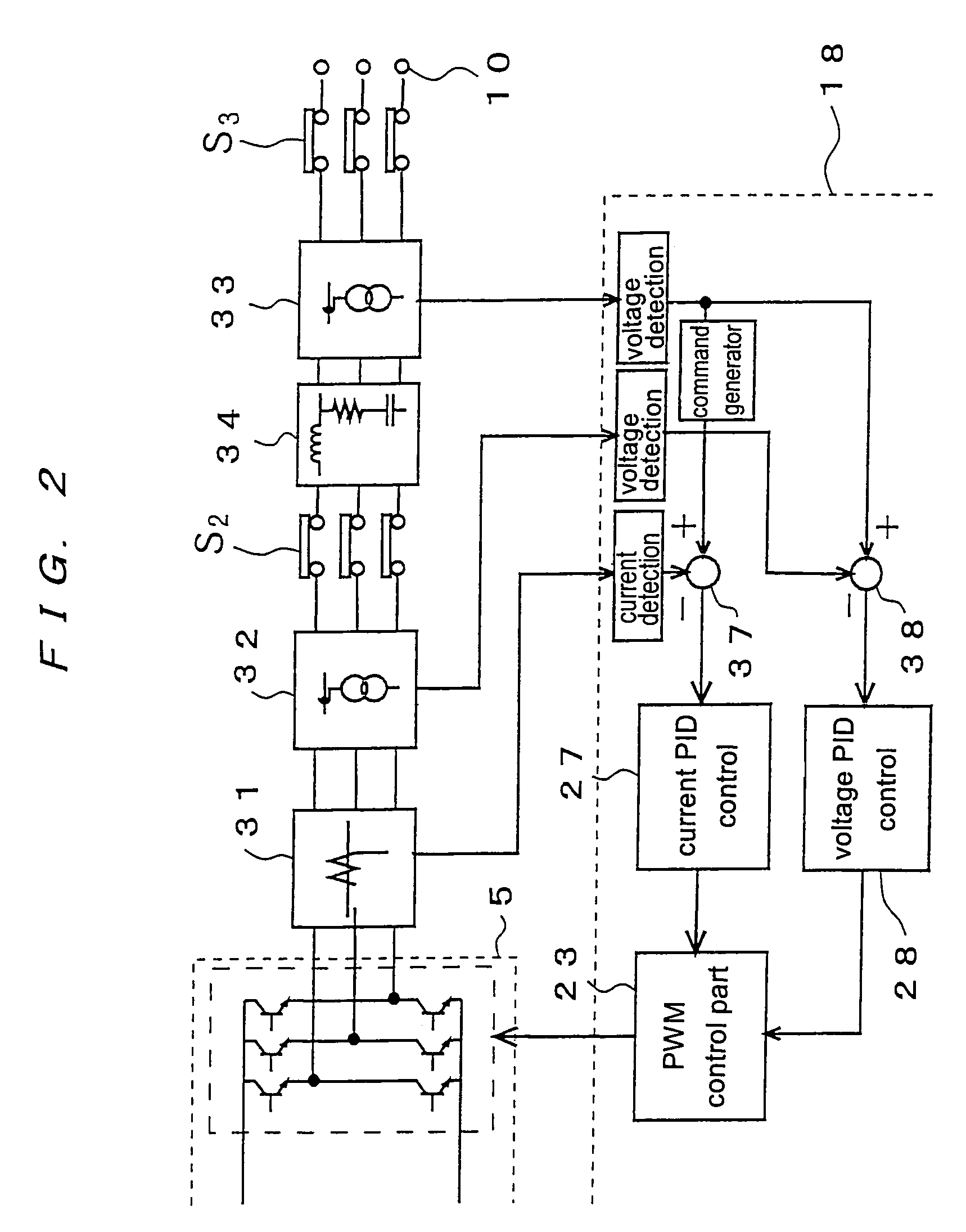
[0009]According to the present invention described above, since the output current of the inverter device is controlled so as to be kept in phase with the voltage of the commercial AC power supply system based on said voltage, the output current supplied from the inverter device to the commercial power supply system is in phase with the voltage of the commercial power supply system. Therefore, electric power at a power factor of 100% can be output to the commercial power supply system. Since no reactive electric power is supplied to the commercial power supply system, the system interconnection can be carried out at a high efficiency.
[0012]Said control device increases an output frequency of said inverter device from zero to a predetermined frequency within a short period of time when said gas turbine is started.
[0013]According to the present invention described above, while the rotational speed of the generator operated as a motor is increased from zero to a predetermined rotational speed by the inverter device, the output current of the inverter device is detected, and the inverter device is controlled to keep the output current constant. Therefore, allowable maximum current can be supplied continuously to the generator operated as a motor. The generator can thus reach the predetermined speed in a shortest period of time within the range of the electric power capacity of the generator.

Problems solved by technology

However, such generating facility has been problematic in that the generating facility is large in size and thus requires a large space for the installation.
Further, a high initial cost is required to introduce the generating facility.

Method used


Image

  • Gas turbine generating apparatus
  • Gas turbine generating apparatus
  • Gas turbine generating apparatus

Examples


Embodiment Construction

[0021]Embodiments of the present invention will be described below with reference to the accompanying drawings.

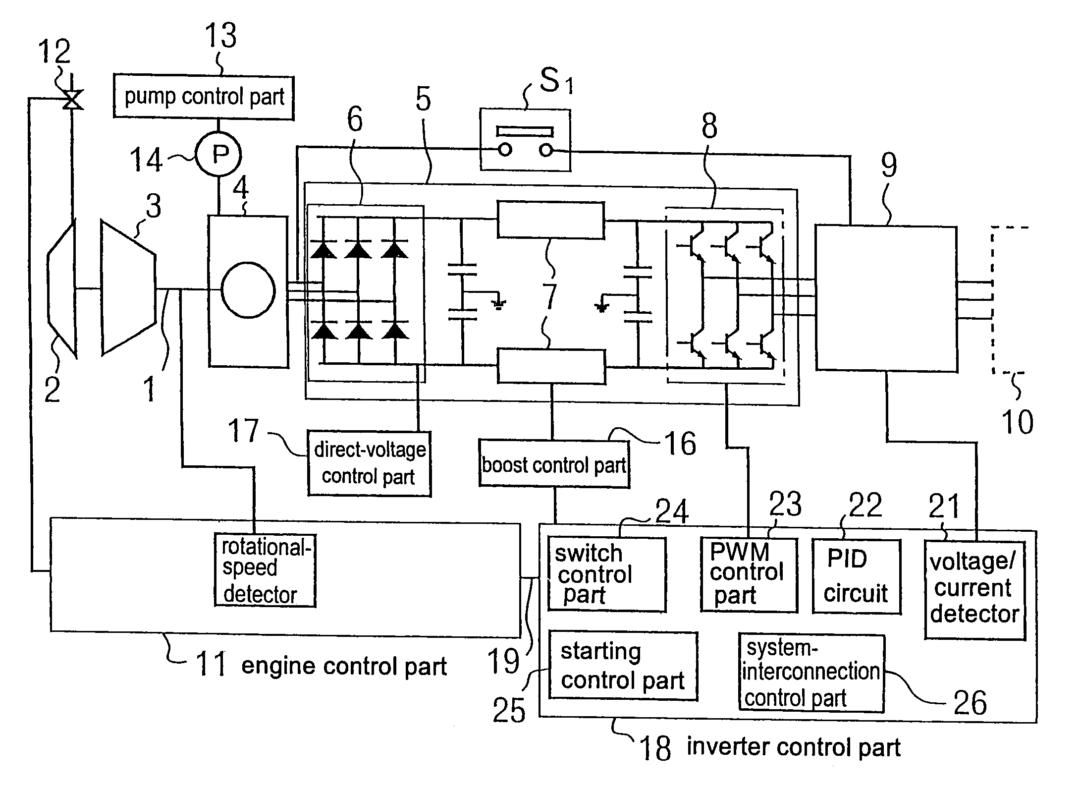
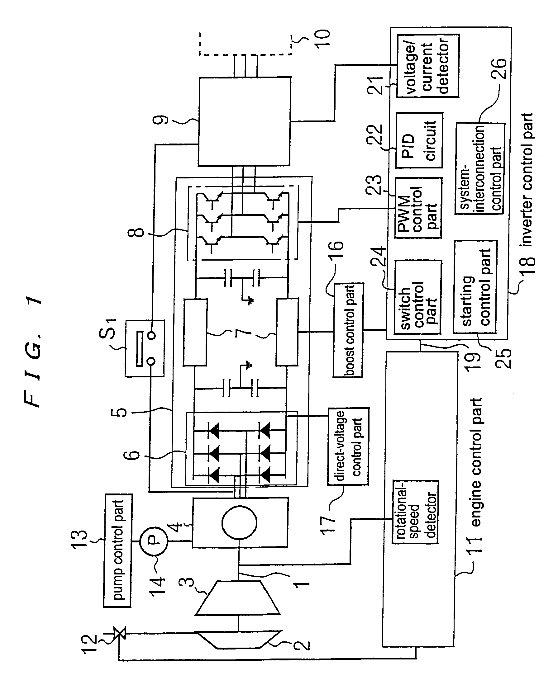
[0022]FIG. 1 is a schematic view showing a control system incorporated in a gas turbine generating apparatus according to an embodiment of the present invention. A turbine generator unit comprises a single rotating shaft 1 to which a turbine rotor 2, a compressor rotor 3, and a rotor of an alternating-current generator 4 are fixed. The alternating-current generator 4 comprises a permanent-magnet-type generator having permanent magnets mounted on a circumferential surface of the rotor. A stator is disposed at a circumferential side of the rotor, and induced voltage generated by the rotation of the rotor is output from windings of the stator. Since the permanent-magnet-type generator is employed, no current loss occurs in the rotor, and hence an excellent generating efficiency can be obtained.

[0023]As described above, the rotating shaft 1 is rotated at a high speed, e.g., of ...


PUM


Abstract

A gas turbine generating apparatus according to the present invention comprises a gas turbine capable of a high-speed operation, a permanent-magnet-type generator driven at a high speed by the gas turbine, an inverter device (5) for converting alternating-current power generated by the generator into commercial alternating-current power, and a system-interconnection device (9) for interconnecting output of the inverter device to a commercial AC power supply system (10). The system-interconnection device controls the inverter device based on voltage of the commercial AC power supply system as a criterion such that output current of the inverter device is in phase with the voltage or out of phase with the voltage by a constant phase difference. A control device (18) is provided for operating the permanent-magnet-type generator (4) as a motor at a time of starting the gas turbine, and supplying alternating-current power from a direct-current power supply through the inverter device or another inverter device in addition to the inverter device to the generator for increasing a rotational speed smoothly from zero. The control device detects output current of the inverter device and controls the inverter device to keep the output current constant.

Description

CROSS-REFERENCE TO RELATED APPLICATIONS[0001]This application is a divisional of U.S. application Ser. No. 10 / 477,750, filed Apr. 6, 2004, now U.S. Pat. No. 6,888,263, which is the National Stage of International Application No. PCT / JP02 / 05009, filed May 23, 2002. The contents of those applications are incorporated herein by reference in their entirety.TECHNICAL FIELD[0002]The present invention relates to a gas turbine generating apparatus, and more particularly to a generating apparatus for generating electric power with the use of a small-sized gas turbine engine capable of a high-speed operation and a generator.BACKGROUND ART[0003]Heretofore, in general, a generating apparatus using a reciprocating engine has been known as a generating facility that can be utilized easily. Such a generating apparatus generates alternating-current power by supplying a fuel such as petroleum to the reciprocating engine to drive a generator that is coupled to the reciprocating engine. Since this typ...

Claims


Application Information

Patent Timeline
Patent Type & Authority Patents(United States)
IPC IPC(8): H02P3/00F01D15/10F02C7/26F02C7/268H02J3/38H02J3/40
CPCF01D15/10F02C7/26F02C7/268H02J3/40H02J3/38F05D2270/06Y02E20/14
Inventor SATOH, MOTOYASUISHIHARA, SEIICHIKINOSHITA, NOBORUOZAWA, TAKAHIDEZHENG, SHAO-JUNMCKELVEY, TERENCEKATAOKA, TADASHI
Owner EBARA CORP
Learn More