Disk array apparatus

a technology of array apparatus and disk, which is applied in the direction of casings/cabinets/drawers, instruments, casings/cabinets/drawers, etc., can solve the problems of large scale of the array apparatus, and achieve the effect of high density, strong demand for size reduction, and effective use of installation spa

Inactive Publication Date: 2006-06-13
HITACHI LTD
View PDF23 Cites 32 Cited by
  • Summary
  • Abstract
  • Description
  • Claims
  • Application Information

AI Technical Summary

Benefits of technology

[0004]On the other hand, the demand for size reduction is also strong for disk array apparatuses for the purpose of effectively using the installation space. The disk array apparatuses are becoming high in density. Therefore, a technique for emitting heat generated in the disk array apparatus to the outside efficiently and cooling the disk array apparatus efficiently is demanded.
[0005]The present invention has been achieved in order to solve the above-described problems. A main object of the present invention is to provide a disk array apparatus having an increased cooling efficiency.
[0007]According to such a mode, the air exhausted from the exhaust planes of the disk boxes, which has cooled the inside of the disk boxes, can be sucked in by the exhaust device in a nearly straight line manner through the draft path formed in the gap. As a result, the draft resistance in the disk array apparatus can be decreased, and the cooling efficiency of the disk array apparatus can be improved.
[0008]Furthermore, since the cooling efficiency is improved, it also becomes possible to reduce the size of the exhaust device. It also becomes possible to reduce the power dissipation, noise, cost and space of the disk array apparatus. In addition, the gap between two opposed disk boxes can be used effectively as a suction space required for the exhaust devices to suck in the air.
[0009]Since it thus becomes unnecessary to provide a dedicated suction space, it becomes possible to reduce the size of the disk array apparatus in the height direction accordingly.

Problems solved by technology

As a result, the disk array apparatuses are becoming large in scale.

Method used


Image

  • Disk array apparatus
  • Disk array apparatus
  • Disk array apparatus

Examples


Embodiment Construction

Configuration of Disk Array Apparatus

[0032]First, a configuration of a disk array apparatus 120 according to the present embodiment will now be described with reference to FIGS. 1 to 4.

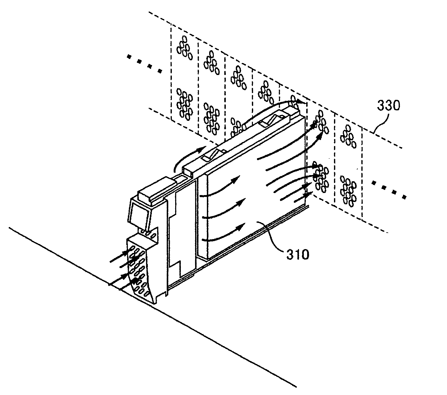
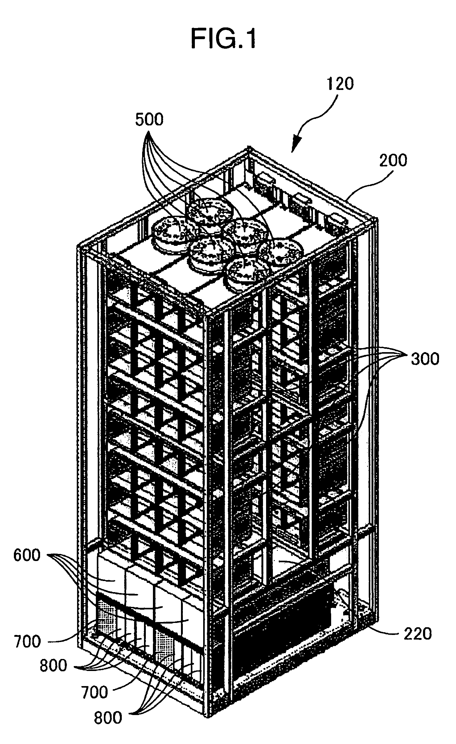
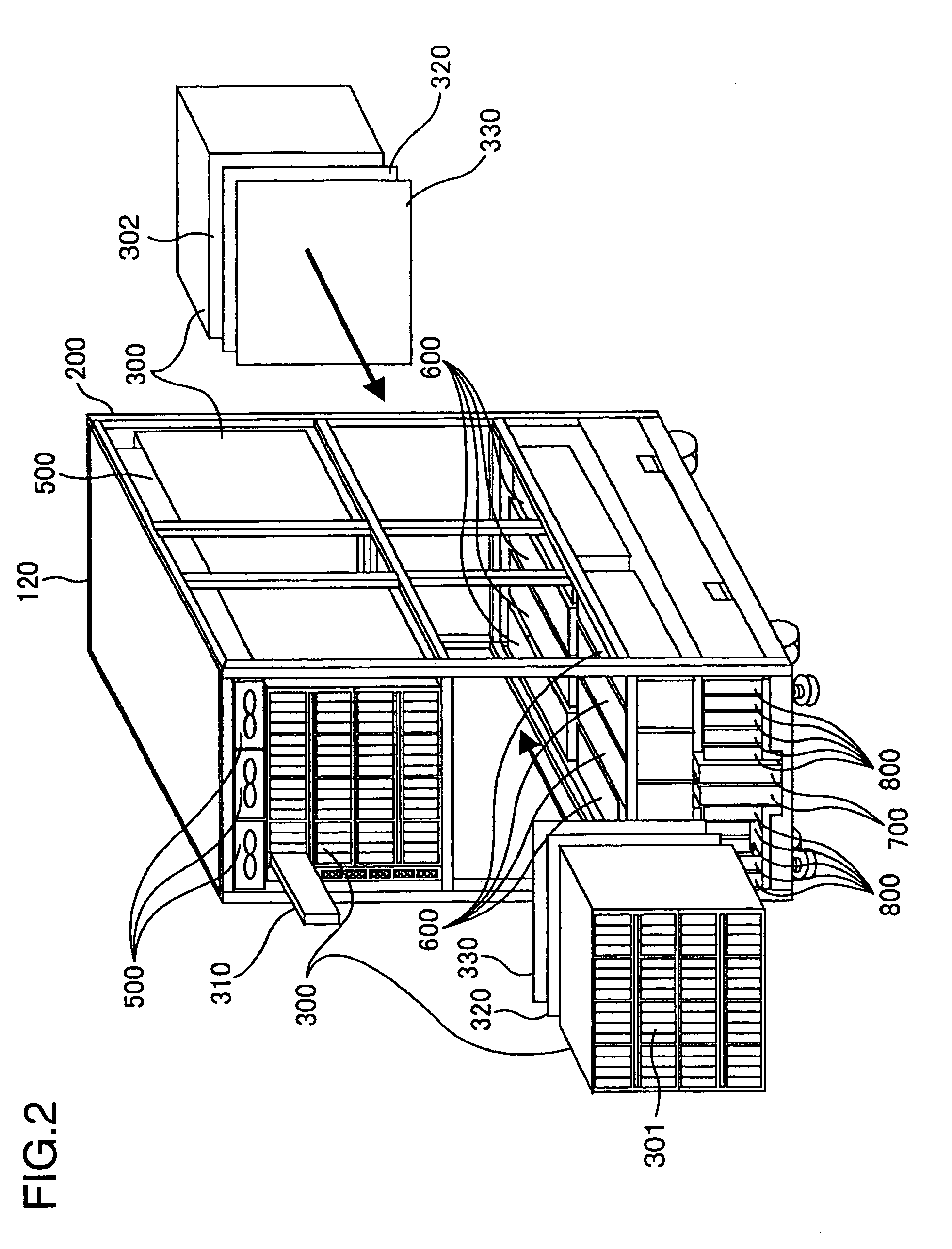
[0033]The disk array apparatus 120 includes disk drive modules (disk boxes) 300, batteries 800, AC-boxes 700, DC power supplies 600, fans (exhausters) 500, and air ducts 210, and an enclosure on a rack 200 for accommodating those components.

[0034]FIG. 1 shows an exterior oblique view diagram of the disk array apparatus 120. FIG. 2 shows how the disk drive modules 300 are accommodated in the rack 200 of the disk array apparatus 120. FIG. 3 is a diagram showing an exterior view of the disk array apparatus 120 obtained by viewing it from the front. FIG. 4 shows an internal configuration of the disk array apparatus 120.

[0035]The rack 200 of the disk array apparatus 120 is broadly divided into three stages, i.e., an upper stage, a middle stage and a lower stage. The disk drive modules 300 are accommodated ...


PUM

PropertyMeasurementUnit
shapeaaaaaaaaaa
widthaaaaaaaaaa
flow rateaaaaaaaaaa

Abstract

Aligned disk drives are installed in a disk box nearly taking a rectangular shape. Every two of the disk boxes are paired and accommodated in a rack in a multi-stage form. Each pair of disk boxes are disposed with their exhaust planes opposed to each other with a gap therebetween. An air intake plane of each disk box opposite to the exhaust is disposed on a front or rear side of the rack. A draft path, having front and rear walls formed by gaps between disk boxes and side walls on left and right planes of the rack, is formed in the rack center. Exhaust fans disposed on top of the rack and having air intake ports nearly equivalent in dimension to a section of the draft path suck in air through the intake and exhaust planes and draft path, and exhaust the air outside the rack.

Description

CROSS-REFERENCE TO RELATED APPLICATION[0001]Japanese Patent Application No. 2003-390209 applied on Nov. 20, 2003 are cited to support the present invention.BACKGROUND OF THE INVENTION[0002]The present invention relates to disk array apparatuses.[0003]In disk array apparatuses used as storage apparatuses in information processing systems, a larger number of disk drives are accommodated because of a demand for an increased storage capacity and higher performance. As a result, the disk array apparatuses are becoming large in scale. Such a disk array apparatus is disclosed in, for example, JP-A-2001-332078.SUMMARY OF THE INVENTION[0004]On the other hand, the demand for size reduction is also strong for disk array apparatuses for the purpose of effectively using the installation space. The disk array apparatuses are becoming high in density. Therefore, a technique for emitting heat generated in the disk array apparatus to the outside efficiently and cooling the disk array apparatus effic...

Claims


Application Information

Patent Timeline
Patent Type & Authority Patents(United States)
IPC IPC(8): G11B33/14G06F1/20G06F3/06G11B33/12H05K7/20
CPCG06F1/20H05K7/20736G11B33/128G11B33/142G11B33/126G06F3/0601G06F2003/0692G06F3/0673
Inventor MIYAMOTO, KENICHIMORISHITA, YASUJIKATAKURA, YASUYUKITANAKA, SHIGEAKIKASAHARA, YOSHIKATSU
Owner HITACHI LTD
Why Eureka
Try Eureka