High magnetic anisotropy hard magnetic bias element

a hard magnetic and anisotropy technology, applied in the field of storage and retrieval of data, can solve the problems of data recovery difficulty, less than perfect alignment of the magnetic moments within the hard magnetic thin film, and degradation of the sensor properties, and achieve the effect of reducing the distortion in the sensor operation

Active Publication Date: 2006-06-13
SEAGATE TECH LLC
View PDF7 Cites 49 Cited by
  • Summary
  • Abstract
  • Description
  • Claims
  • Application Information

AI Technical Summary

Benefits of technology

[0009]A magnetoresistive sensor with an MR stack biased by high anisotropy hard bias elements has reduced distortion in sensor operation from misaligned magnetic moments. The high anisotropy hard bias elements are formed from a hard magnetic material deposited in a thin film having a plurality of magnetic grains. Each magnetic grain has a substantially axial preferred direction of magnetic anisotropy even without application of a setting field. The axis is determined by the deposition method and optional seedlayer(s). The magnetic anisotropy is directed in the hard magnetic material by oblique deposition in a direction approximately normal to the preferred direction of anisotropy in the resulting hard bias element. The magnetization of the hard magnetic material is unidirectionally aligned along the preferred anisotropy axis by application of a unidirectional setting field.

Problems solved by technology

To operate the MR sensor properly, the sensor must be stabilized against the formation of edge domains because domain wall motion results in electrical noise that makes data recovery difficult.
Due to the random orientation of each grain's magnetic moment in the unset film, some grains resist the setting field more than others and can produce less than perfect alignment of the magnetic moments within the hard magnetic thin film.
Imperfect alignment within the hard magnetic thin film of the biasing elements can lead to a degradation of sensor properties, including head-to-head comparisons of amplitude, noise and glitching.
However, distortion caused by misalignment of single grains within the hard magnetic bias elements increases head-to-head variation.
The result is reduced manufacturing yield, increased production cost and potentially increased field failure rates.

Method used


Image

  • High magnetic anisotropy hard magnetic bias element
  • High magnetic anisotropy hard magnetic bias element
  • High magnetic anisotropy hard magnetic bias element

Examples


Embodiment Construction

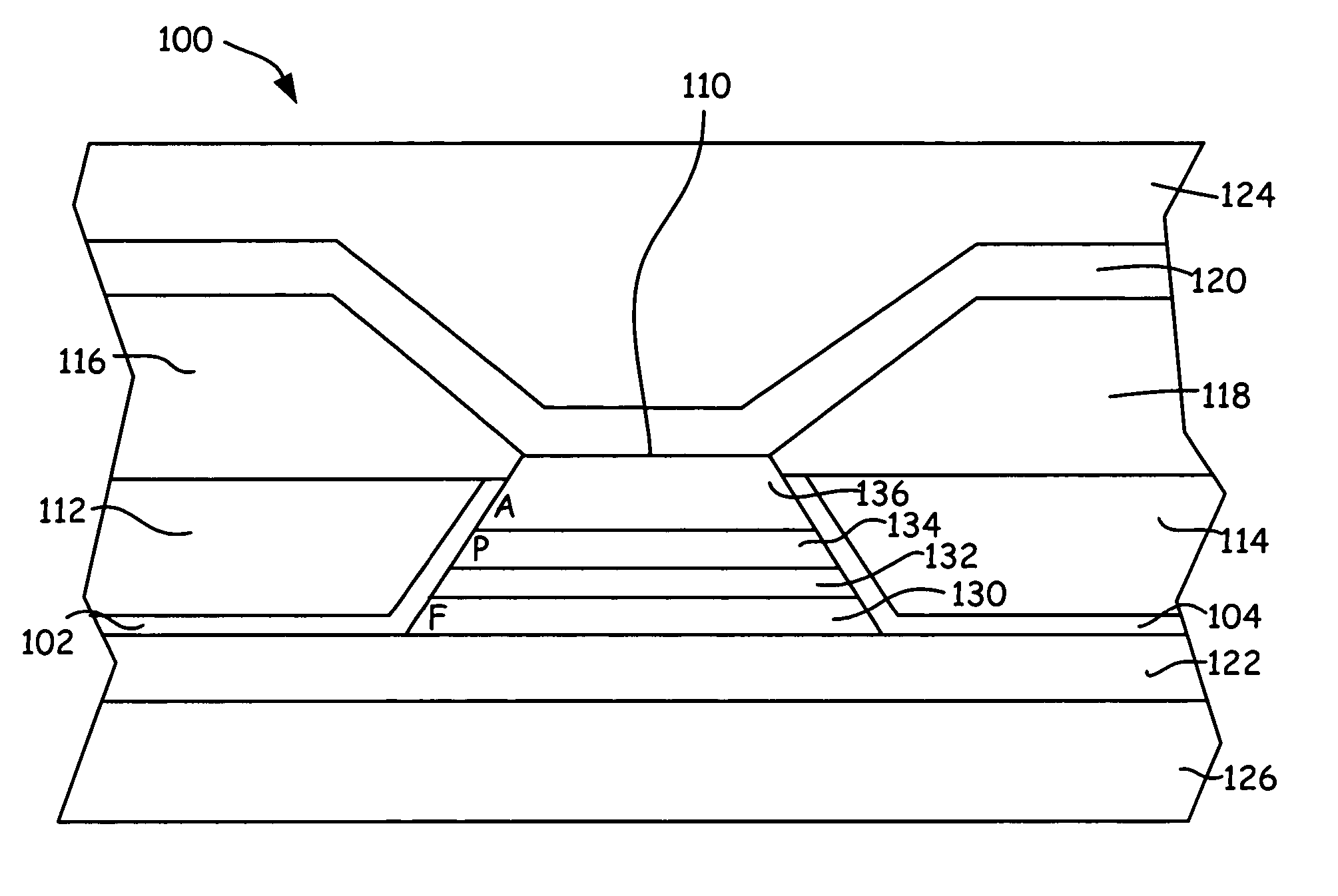
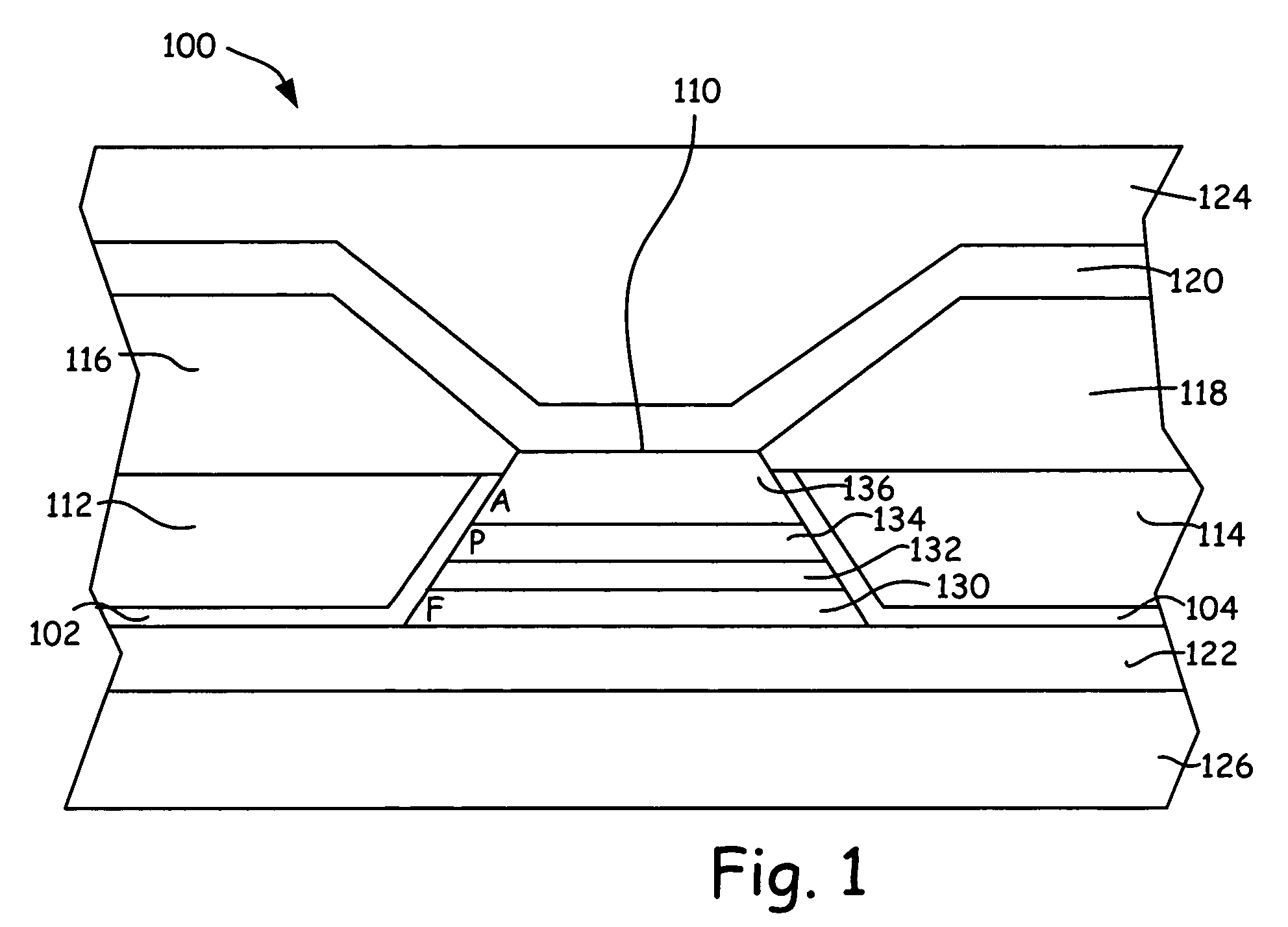
[0029]FIG. 1 is a cross-sectional view of a first example transducing head 100 with high anisotropy bias elements in accord with the present invention. Transducing head 100 is a current-in-plane (CIP) type head which includes first and second permanent magnet (PM) seed layers 102 and 104, magnetoresistive (MR) sensor 110, first and second high anisotropy permanent magnet (PM) bias elements 112 and 114, first and second contacts 116 and 118, top and bottom insulating layers 120 and 122, and top and bottom shields 124 and 126.

[0030]MR sensor 110 is a multilayer device operable to sense magnetic flux from a magnetic media. MR sensor 110 may be any one of a plurality of MR-type sensors, including, but not limited to, AMR, GMR, TMR, spin-valve and spin-tunnel sensors. At least one layer of MR sensor 110 is a sensing layer that requires longitudinal biasing, such as a free layer of a GMR spin-valve sensor. Moreover, for several types of MR sensors, at least one layer of MR sensor 110 is a...


PUM

PropertyMeasurementUnit
angleaaaaaaaaaa
angleaaaaaaaaaa
angleaaaaaaaaaa

Abstract

A magnetoresistive sensor having an MR stack biased by high anisotropy hard bias elements thereby reducing distortion in sensor operation and improving head to head operational values. The high anisotropy hard bias elements are formed from a hard magnetic material deposited in a thin film having a substantially axial preferred direction of magnetic anisotropy prior to application of a setting field. The magnetic anisotropy in the hard magnetic material is formed by oblique deposition in a direction approximately normal to the preferred direction of anisotropy in the resulting hard bias element.

Description

BACKGROUND OF THE INVENTION[0001]The present invention relates generally to the field of storage and retrieval of data within magnetic media. In particular, the present invention relates to high magnetic anisotropy in hard magnetic bias elements of magnetoresistive sensing elements.[0002]A transducing head of a magnetic data storage and retrieval system typically includes a magnetoresistive (MR) reader portion for retrieving magnetic data stored on a magnetic media. The reader is formed of multiple layers which include an MR sensor generally positioned between two insulating layers, which are in turn positioned between two shield layers. The MR sensor may be any one of a plurality of MR-type sensors, including, but not limited to, anisotropic magnetoresistive (AMR), giant magnetoresistive (GMR), tunneling giant magnetoresistive (TMR), spin-valve, and spin-tunnel sensors.[0003]When the transducing head is placed near a magnetic medium, resistance of the MR sensor changes in response ...

Claims


Application Information

Patent Timeline
Patent Type & Authority Patents(United States)
IPC IPC(8): G11B5/127G11B5/33G11B5/49
CPCG11B5/493
Inventor LARSON, DAVID J.SINGLETON, ERIC W.MACKEN, DECLANMORAN, PATRICK J.
Owner SEAGATE TECH LLC
Why Eureka
Try Eureka