Optical recording method and apparatus for an optical storage medium

a recording method and optical storage medium technology, applied in the field of optical storage medium optical recording methods and apparatuses, can solve the problems of many control parameters that must be controlled, deterioration of jitter that is unexpectedly serious, and inability to improve jitter, so as to achieve convenient recording power control, prevent deterioration of jitter sufficiently, and achieve the effect of convenient operation

Inactive Publication Date: 2006-06-13
RICOH KK
View PDF23 Cites 13 Cited by
  • Summary
  • Abstract
  • Description
  • Claims
  • Application Information

AI Technical Summary

Benefits of technology

[0027]In the optical recording method and apparatus of the above preferred embodiments, the first and second write powers, allocated to the pulses of the recording pulse pattern, are linearly varied in proportion with a change of the recording linear velocity, and the first and second write powers are expressed as a continuous linear function of the recording linear velocity. Hence, the recording power control can be easily performed and the deterioration of the jitter can be sufficiently prevented. The optical recording method and apparatus of the present invention are effective in easily performing the high-speed recording of the optical storage medium at a high recording speed above the basic recording speed by setting the recording pulse pattern so as to match with either the constant-angular-velocity recording process or the variable-linear-velocity recording process.

Problems solved by technology

Generally, if the recording pulsewidth is solely controlled in accordance with the recording linear velocity so as to cover a required range of the recording linear velocity (e.g., the range between the basic recording speed and the 2.5-times higher recording speed), the effect to improve the jitter is apt to become inadequate.
If many control parameters must be controlled or the setting of control parameters is complicated, small errors of the individual control parameters in combination will be significant, which causes the deterioration of the jitter that is unexpectedly serious.
Therefore, when the recording pulsewidth is controlled in accordance with the recording linear velocity or the recording position, there is a problem in that many control parameters must be controlled or the setting of control parameters is complicated.
If the control parameter is not expressed as a continuous linear function, the optimum control parameter does not have a constant value for an error of the recording linear velocity (or the recording position), it is rapidly fluctuated, and the deterioration of the jitter is not prevented sufficiently.
If the control parameter is expressed as a discontinuous function, the optimum control parameter is rapidly fluctuated for an error of the recording linear velocity, and the deterioration of the jitter is not prevented sufficiently.
However, if the (n−2) multi-pulse recording scheme is used at the 2.5-times higher recording speed, the energy of the recording light needed to record short marks at the outer tracks of the disk will be insufficient.
In the above case, it is difficult to obtain the recording characteristics (in particular, the recording of short marks on the disk) that are equivalent to those obtained at the basic recording speed.
However, the range of the recording pulsewidth that can be adjusted in the multi-pulse waveform is limited.
It is very difficult to make the time duration between the rising edge of the last pulse and the trailing edge of the last middle pulse within the multi-pulse waveform infinitely approach zero.
Hence, it is very difficult to make the above method of the continuous switching feasible.
However, it is very difficult to make the pulsewidth of the last pulse (or the top pulse) within the multi-pulse waveform infinitely approach zero.
Hence, it is very difficult to make the above method of the continuous switching feasible.

Method used


Image

  • Optical recording method and apparatus for an optical storage medium
  • Optical recording method and apparatus for an optical storage medium
  • Optical recording method and apparatus for an optical storage medium

Examples


Embodiment Construction

[0040]A description will now be provided of preferred embodiments of the present invention with reference to the accompanying drawings.

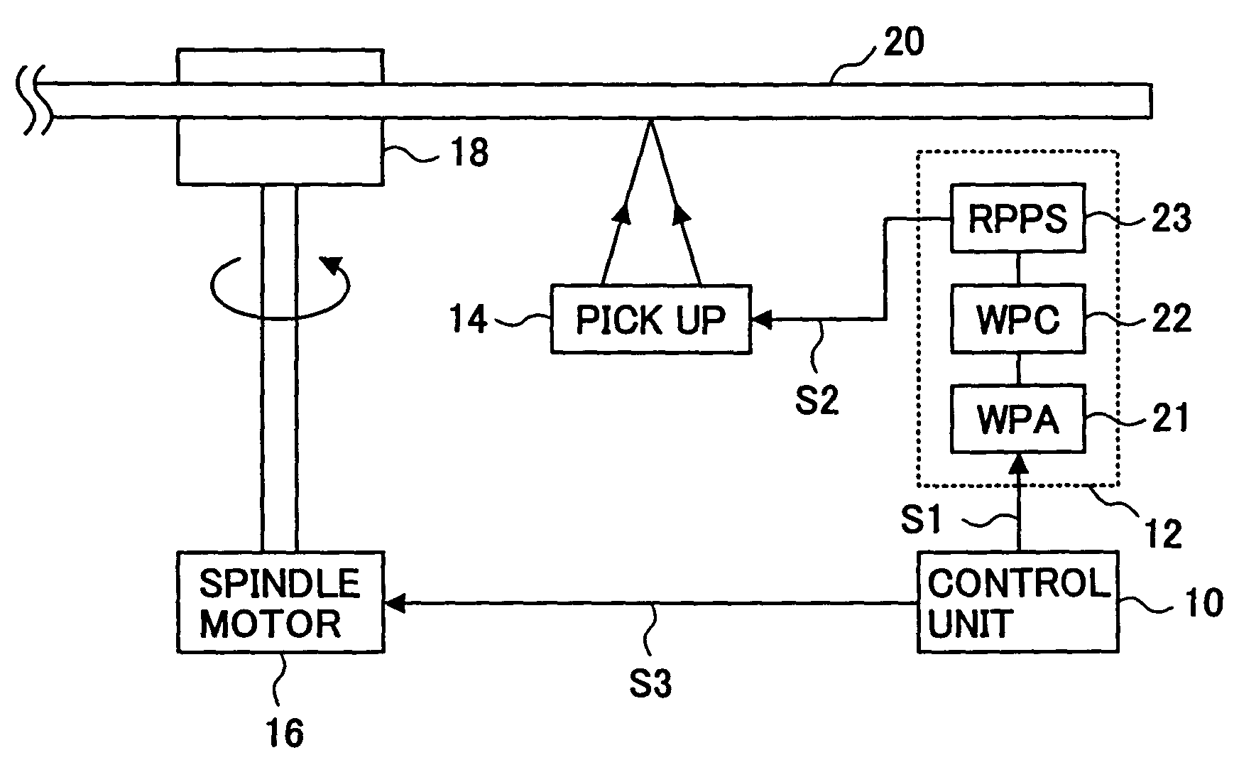
[0041]FIG. 11 shows an optical recording apparatus which carries out one embodiment of the optical recording method of the present invention.

[0042]As shown in FIG. 11, the optical recording apparatus of the present embodiment generally includes a control unit 10, a recording pulse pattern generator 12, a pickup 14, a spindle motor 16, and a turntable 18. The recording pulse pattern generator 12 includes a write power allocation unit (“WPA”) 21, a write power control unit (“WPC”) 22, and a recording pulse pattern supply unit (“RPPS”) 23.

[0043]Suppose that, in the optical recording apparatus of FIG. 11, a high-density optical storage medium 20 (for example, a DVD) is placed onto the turntable 18, and, during recording or reproducing operation of the optical recording apparatus, the storage medium 20 is rotated at a given rotation speed by the spindle m...


PUM

PropertyMeasurementUnit
thicknessaaaaaaaaaa
thicknessaaaaaaaaaa
recording frequencyaaaaaaaaaa

Abstract

In an optical recording method and apparatus for an optical storage medium, a recording pulse pattern having a sequence of multiple pulses is used to record one of plural kinds of marks with different lengths on the storage medium through a variable-linear-velocity recording process or a constant-angular-velocity recording process. Two or more discrete write powers are individually allocated to the respective pulses of the recording pulse pattern. Each of the write powers, allocated to the respective pulses of the recording pulse pattern, is linearly varied in proportion with a change of one of the recording linear velocity and a recording position of the storage medium. The resulting recording pulse pattern is supplied to a pickup, and the pickup emits a light beam to the storage medium in accordance with the recording pulse pattern having the linearly varied write powers allocated to the respective pulses, so that one of the plural kinds of marks is recorded on the storage medium.

Description

[0001]This application is a continuation of application Ser. No. 09 / 722,689 filed on Nov. 28, 2000, now U.S. Pat. No. 6,628,595, which claims priority under 35 U.S.C. 119 to the following foreign application: Japanese Application No. 11-338613, dated Nov. 29, 1999, the disclosure of both of which are hereby incorporated by reference.BACKGROUND OF THE INVENTION[0002]1. Field of the Invention[0003]The present invention generally relates to an optical recording method and apparatus for an optical storage medium, and more particularly to an optical recording method and apparatus that achieves the recording of a high-density optical storage medium at a high recording speed above a basic recording speed by setting the recording pulse pattern so as to match with either a constant-angular-velocity recording process or a variable-linear-velocity recording process.[0004]2. Description of the Related Art[0005]As disclosed in Japanese Laid-Open Patent Application No.11-232652, an optical record...

Claims


Application Information

Patent Timeline
Patent Type & Authority Patents(United States)
IPC IPC(8): G11B7/00G11B7/0045G11B7/125
CPCG11B7/00456G11B7/1267G11B7/1263
Inventor SASA, NOBORUTOMURA, TATSUYANOGUCHI, SOHSATOH, TSUTOMUUENO, YASUNOBUHIGASHI, YASUHIRO
Owner RICOH KK
Why Eureka
Try Eureka