
Optical recording medium and recording method for the same

a technology applied in the field of optical recording medium and information layer recording method, can solve the problems of not being able to selectively break and remove only the information layer, bca signal cannot be obtained insufficient degree, and it is impossible to record

Inactive Publication Date: 2006-06-13
PANASONIC CORP
View PDF39 Cites 55 Cited by
  • Summary
  • Abstract
  • Description
  • Claims
  • Application Information

AI Technical Summary

Benefits of technology

This configuration allows for stable recording of BCA patterns, reduces defects, and lowers manufacturing costs by enabling precise recognition and recording of medium identification information without altering the information layer's shape, thus improving the security and reliability of optical discs.

Problems solved by technology

However, when the method for forming a BCA pattern by breaking and removing a reflective layer in a reproduction-only type optical recording medium is to be applied to an optical disc, the following problems arise.
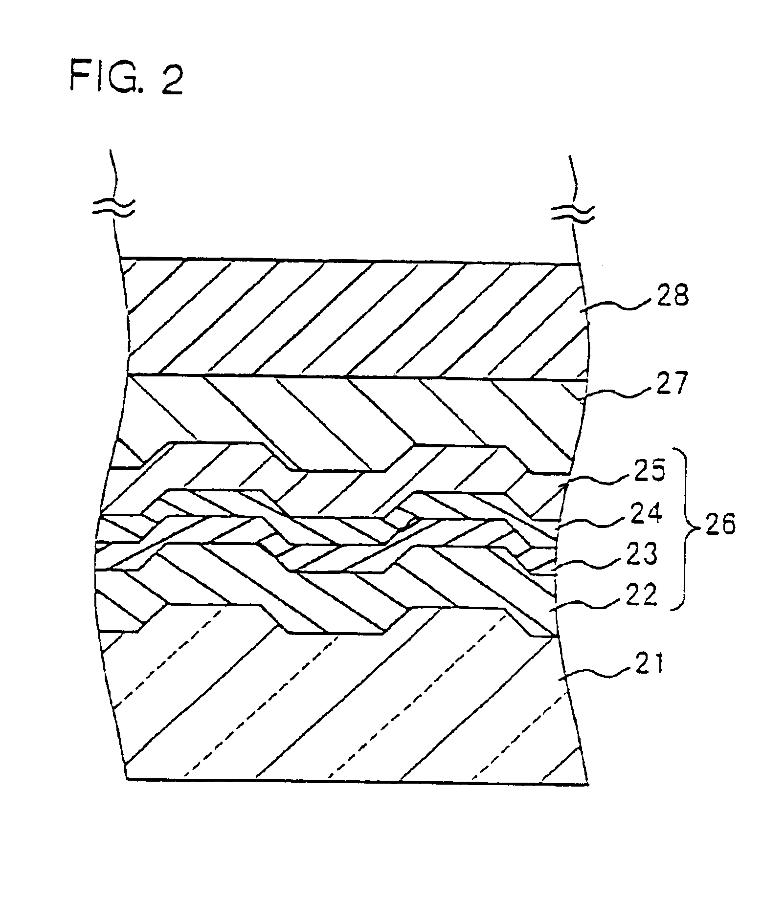
Next, even if the method for forming a BCA pattern in a reproduction-only type optical recording medium is applied by emitting a laser beam pulse-like in accordance with the BCA pattern so as to break and remove the information layer in the optical disc, it is not possible to selectively break and remove only the information layer containing a photoactive material, since a laminated film such as an enhancement layer, a hard layer, an intermediate layer, or a dielectric layer is formed at least on one side of the information layer.
As a result, the information layer and / or the laminated film in the vicinity of the boundary of the BCA pattern may be separated, or particle of the information layer and / or the laminated film arising inside the BCA pattern may cause distortion in forming the BCA pattern part, which leads to the problem that BCA signals cannot be obtained sufficiently due to noise mixed in the signals for detecting the BCA.
Furthermore, the defect caused by the separation of the information layer and / or the laminated film in the vicinity of the BCA pattern is not confined to the subsidiary information area but reaches the information layer and / or the laminated film of the main information area, which is a critical problem for the recording-type optical recording medium.
Accordingly, the defect spreads to the subsidiary information area and also to the information layer in the main information area, thereby increasing the factors of causing critical defects that make it impossible to record.
Thus, it is difficult to record BCA patterns that can be detected exactly at least in the recordable type optical disc.
One of the main reasons for the increase in the manufacturing costs of optical discs is the problem related to the formation of BCA patterns.

Method used


Image

  • Optical recording medium and recording method for the same
  • Optical recording medium and recording method for the same
  • Optical recording medium and recording method for the same

Examples


embodiment 1

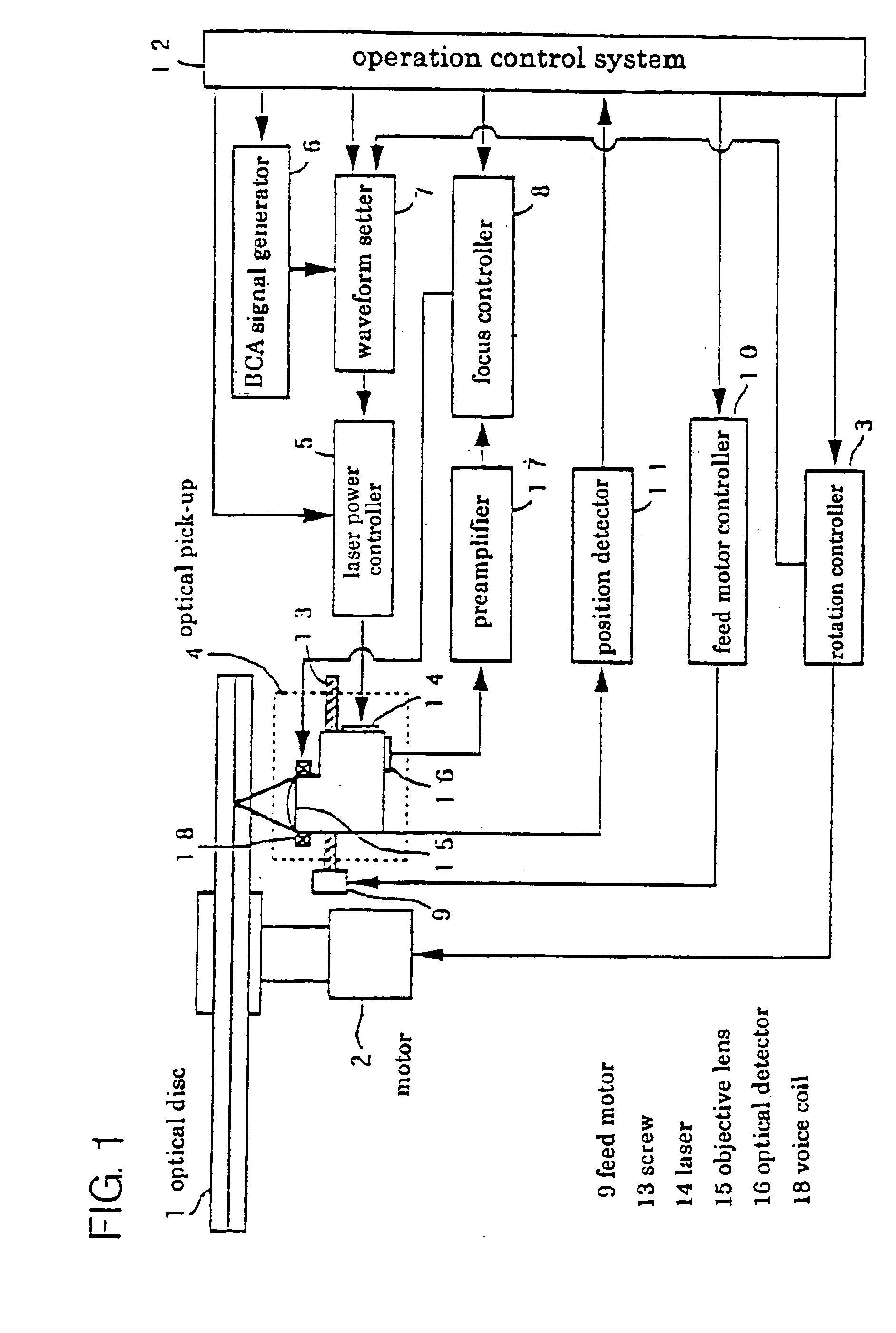
[0063]FIG. 1 is a block diagram showing an example of a device for recording medium identification information in an optical disc. It will be explained with regard to BCA as the medium identification information. The recording device of FIG. 1 includes a spindle motor 2 for rotating an optical disc 1, a rotation controller 3, an optical pick-up 4 for focusing light beams generated from a light source such as a laser, a laser power controller 5 for driving the light source of the optical pick-up 4, a BCA signal generator 6 for generating a BCA signal by modulating subsidiary information to be recorded on the optical disc, a waveform setter 7 for reshaping the laser modulation waveform based on the BCA signal, a focus controller 8 for focusing the light emitted from the optical pick-up 4 on the optical disc, a feed motor 9 for shifting the optical pick-up 4 and a feed motor controller 10, a position detector 11 for detecting the position of the optical pick-up 4, and an operation cont...

embodiment 2

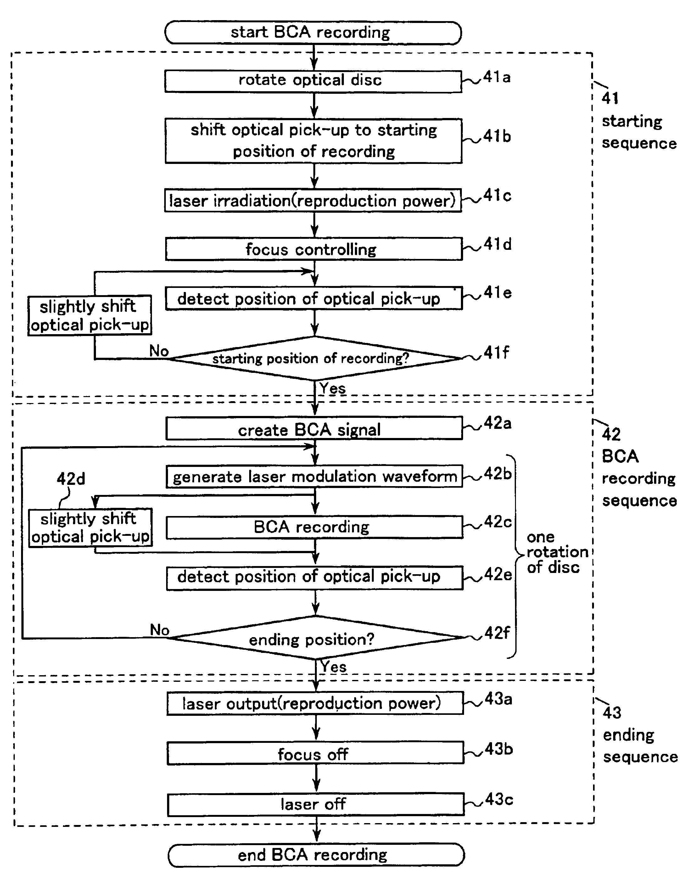
[0078]FIG. 8 is a block diagram showing the configuration of a BCA recording device of the present invention, which is capable of recording BCA in an optical disc and also of initializing the optical disc continuously. This recording device is characterized in that the BCA recording and the initialization of the optical disc 1 can be performed continuously by adding a BCA recording control system 81, an initialization control system 82 and a switching device 83 for switching the respective control system in accordance with the situation to the BCA recording device illustrated in FIG. 1. This switching device 83 of the BCA recording and the initialization is operated according to the signal sent from the position detector 11, in which the switching device allows the BCA recording control system to take the control of the system when the position of the light beam is within the subsidiary information recording area, whereas the switching device allows the initialization control system...

embodiment 3

[0089]With the use of the device shown in FIG. 8, a method for recording a BCA pattern by providing a through hole that penetrates a recording layer and / or a recording film or a depression hole (hereinafter referred to as a hole) will be explained. According to the present invention, compared with the conventional method for recording a BCA pattern by using one laser emission for one BCA pattern, a light beam is emitted for several times to form a light spot that is sufficiently smaller than the BCA pattern, so that the thermal influence and the thermal damage to the recording film and to its peripheral portion can be reduced, thereby forming excellent holes (BCA patterns). Furthermore, as illustrated in FIG. 11, this method can be accomplished by increasing the power of the laser beam to such a power 111a that the film starts to break in the part of BCA recording. According to this method, it is possible to initialize the optical disc and also to record BCA by making holes in the r...


PUM

PropertyMeasurementUnit
diameteraaaaaaaaaa
diameteraaaaaaaaaa
diameteraaaaaaaaaa

Abstract

A main information area 31 capable of recording an information signal and a subsidiary information area 32 for recording subsidiary information that is different from the information signal are divided in one principal plane direction of a substrate, and an information layer for recording the information signal in the main information area 31 is provided also in the subsidiary information area 32, and medium identification information for distinguishing the medium optically is recorded in the information layer of the subsidiary information area 32 without changing the shape of the information layer. As a result, the medium identification information can be recorded in an optical recording medium 1 stably. In particular, the initialization of a phase change type optical recording medium and the recording of the medium identification information can be performed at the same time, so that the production process can be simplified, and the production costs can be reduced.

Description

TECHNICAL FIELD[0001]The present invention relates to an optical recording medium and a method for recording information in the optical recording medium.BACKGROUND ART[0002]In recent years, the amount of information to be recorded in a single optical recording medium has been increasing, and the distribution of information recorded in optical recording media as software information has been promoted. The technology to prevent illegal copying thereof also has developed. Therefore, as so-called security measures, identification information is desired to be recorded respectively in optical recording media.[0003]To meet this requirement, the technique generally applied to record identification information for optical recording media is, for example, to provide a pit part of a reproduction-only type optical recording medium with an additional area (Burst Cutting Area, hereinafter abbreviated as “BCA”) where bar-codes are overwritten, so that identification information (ID) and, if necess...

Claims


Application Information

Patent Timeline
Patent Type & Authority Patents(United States)
IPC IPC(8): G11B7/00G11B7/24G11B7/0045G11B7/007G11B7/125G11B7/26G11B19/12G11B20/00G11B20/12G11B20/18
CPCG11B7/0045G11B7/007G11B7/00736G11B7/126G11B7/24G11B7/26G11B7/265G11B7/268G11B19/12G11B19/122G11B20/00086G11B20/00268G11B20/00876G11B20/1217G11B20/18G11B20/1883G11B2220/20G11B7/00454
Inventor IRIE, HIROAKIHORAI, KEIICHIRONISHIUCHI, KENICHIFUKUSHIMA, YOSHIHISAOSHIMA, MITSUAKI
Owner PANASONIC CORP
Learn More