Designing boundary filters for a biorthogonal filter bank

a biorthogonal filter and design technique, applied in the field of biorthogonal filter bank design, can solve the problems of non-ideal behavior at the boundary, inability to guarantee certain properties, and long-serving boundary filter design techniques, so as to facilitate the selection of appropriate boundary filters

Active Publication Date: 2006-06-13
TEXAS INSTR INC
View PDF0 Cites 2 Cited by
  • Summary
  • Abstract
  • Description
  • Claims
  • Application Information

AI Technical Summary

Benefits of technology

[0005]Particular embodiments of the present invention may provide one or more technical advantages. Particular embodiments may facilitate selection of appropriate boundary filters for an analysis portion of a filter bank. In particular embodiments, boundary filters may be chosen to satisfy a number of criteria, such as frequency selectivity or number of vanishing moments, and need only be linearly independent of the filters of the original filter bank. In particular embodiments, a synthesis filter bank is found by calculating the dual of an analysis filter ba

Problems solved by technology

Signal extension techniques are computationally simple, but generally result in an expansive filter bank (which may result in more sub-band coefficients than the original length of the input signal) and exhibit non-ideal behavior at the bo

Method used


Image

  • Designing boundary filters for a biorthogonal filter bank
  • Designing boundary filters for a biorthogonal filter bank
  • Designing boundary filters for a biorthogonal filter bank

Examples


Embodiment Construction

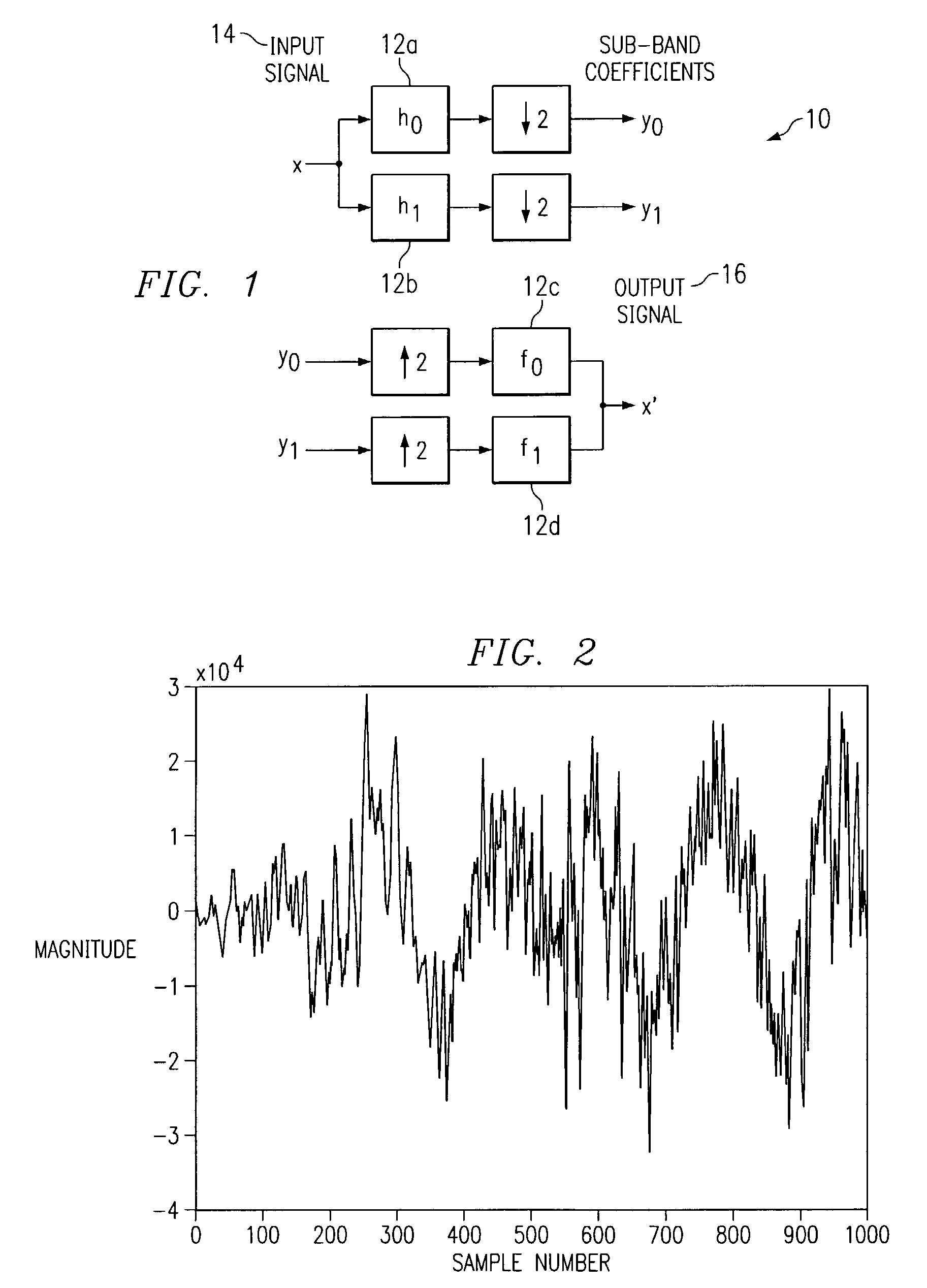
[0012]FIG. 1 illustrates an example two-channel filter bank 10. Filter banks can be interpreted from a linear algebra perspective, which may provide a powerful and notationally compact representation of filter banks. Although an example two-channel filter bank is described for the sake of simplicity, the present invention contemplates a filter bank including any suitable number of channels. Analysis filter bank 10 may include filters 12. Filter 12a may be designated as filter h0, filter 12b may be designated as filter h1, filter 12c may be designated as filter f0, and filter 12b may be designated as filter f1. Filters h0 and h1 are analysis (i.e. decomposition) filters and may, respectively, be a low-pass filter and a high-pass filter. Collectively, analysis filters h0 and h1 form an analysis filter bank. Filters f0 and f1 are synthesis (i.e. reconstruction) filters. Collectively, filters f0 and f1 form a synthesis filter bank. In a perfect reconstruction (PR) filter bank 10, an inp...


PUM


Abstract

A signal processing device includes a biorthogonal filter bank that processes a finite length signal including a left boundary and a right boundary. The biorthogonal filter bank includes an analysis filter bank. The analysis filter bank includes one or more left boundary filters, one or more right boundary filters, and one or more steady-state analysis filters. Each left boundary filter and each right boundary filter includes a row vector. The left and right boundary filters have been designed by generating, from the steady-state analysis filters, an analysis matrix representing the analysis filter bank, multiplying the analysis matrix by a permutation matrix to generate a permutated analysis matrix, truncating the permutated analysis matrix to a degree to generate a rectangular truncated analysis matrix, and selecting a number of left boundary filters and a number of right boundary filters such that, when the row vectors corresponding to the number of left boundary filters and the number of right boundary filters are added to the truncated analysis matrix, the truncated analysis matrix becomes square. Each row vector added to the truncated analysis matrix lies outside a row space of the truncated analysis matrix such that a row vector specifies a permissible design for a boundary filter. The biorthogonal filter bank also includes a synthesis filter bank corresponding to the analysis filter bank. The synthesis filter bank includes a number of left boundary filters, a number of right boundary filters, and a number of steady-state synthesis filters. A synthesis matrix specifies the left boundary filters, right boundary filters, and steady-state synthesis filters of the synthesis filter bank. The synthesis matrix has been created by calculating the dual, or inverse, of the square analysis matrix.

Description

TECHNICAL FIELD OF THE INVENTION[0001]This invention relates generally to designing filter banks and more particularly to designing boundary filters for a biorthogonal filter bank.BACKGROUND OF THE INVENTION[0002]Many applications in multi-rate digital signal processing require the analysis of input signals that are finite in length. Multi-rate filter banks provide an excellent and efficient means of analyzing input signals that are infinite in length, but have stumbled when the input signal is finite in length. Filter banks for signals finite in length have been extensively studied, and solutions to this problem include boundary filter design and signal extension techniques. Signal extension techniques are computationally simple, but generally result in an expansive filter bank (which may result in more sub-band coefficients than the original length of the input signal) and exhibit non-ideal behavior at the boundaries. Boundary filter design techniques are length-preservative, but ...

Claims


Application Information

Patent Timeline
IPC IPC(8): G10L19/00G06F17/10G10L21/00H03H17/02
CPCH03H17/0266
Inventor ZELAZO, DANIEL L.
Owner TEXAS INSTR INC
Why Eureka
Try Eureka