Combustion chamber with flameless oxidation

a combustion chamber and flameless technology, applied in the direction of indirect carbon-dioxide mitigation, combustion process, lighting and heating apparatus, etc., can solve the problems of inability to achieve flame collapse and blowback, in principle impossibl

Inactive Publication Date: 2006-06-20
WS WARMEPROZESSTECHN
View PDF6 Cites 54 Cited by
  • Summary
  • Abstract
  • Description
  • Claims
  • Application Information

AI Technical Summary

Benefits of technology

[0009]To form flameless oxidation while simultaneously achieving a combustion chamber with low flow resistance and a compact design, the fuel is introduced to the combustion chamber in the same direction as the fresh air. As a result, local eddies, which otherwise might contribute to an increase in pressure loss, are largely reduced.

Problems solved by technology

Flame collapse and blowback are, in principle, impossible.

Method used


Image

  • Combustion chamber with flameless oxidation
  • Combustion chamber with flameless oxidation
  • Combustion chamber with flameless oxidation

Examples


Embodiment Construction

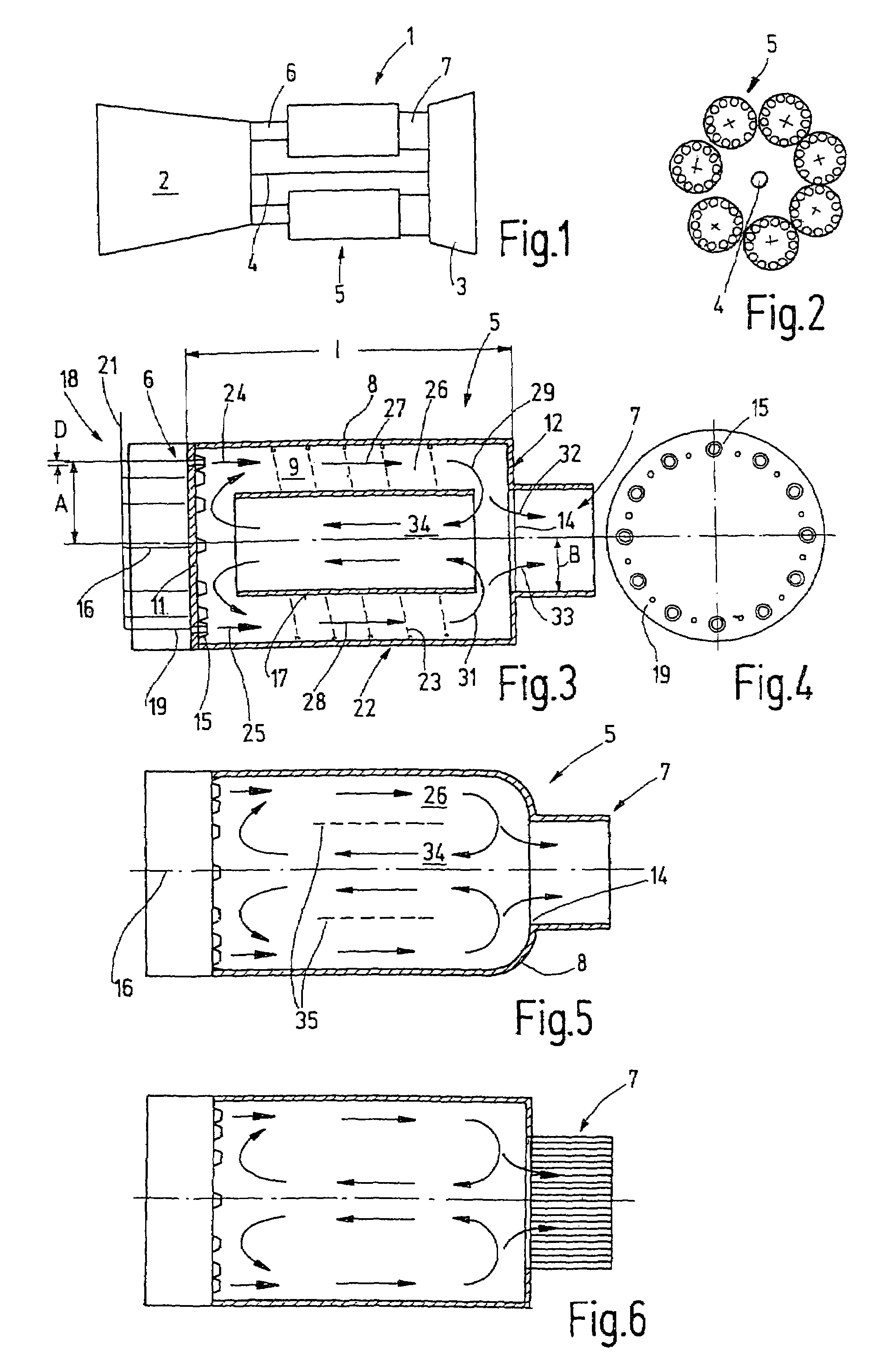
[0027]A gas turbine 1 having a compressor 2, a turbine 3, which is connected to the compressor 2 via a shaft 4, and at least one combustion chamber 5, is shown in FIG. 1. Each combustion chamber has an inlet 6, which is fed compressed air from compressor 2, and an outlet 7, which supplies the gas stream generated in combustion chamber 5 to turbine 3.

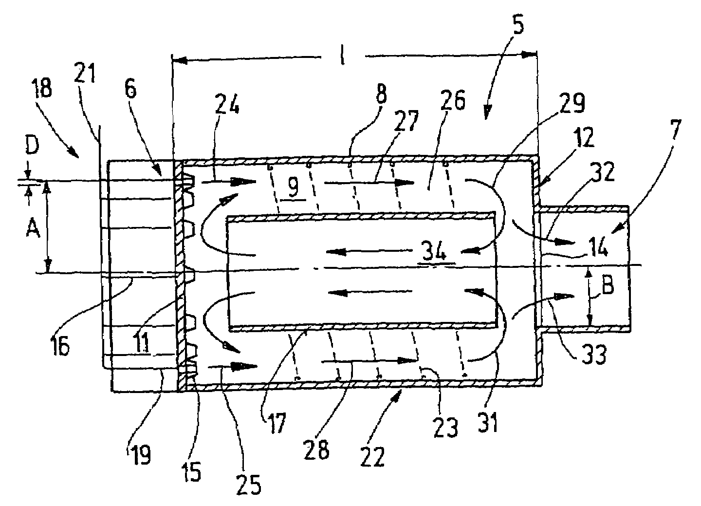
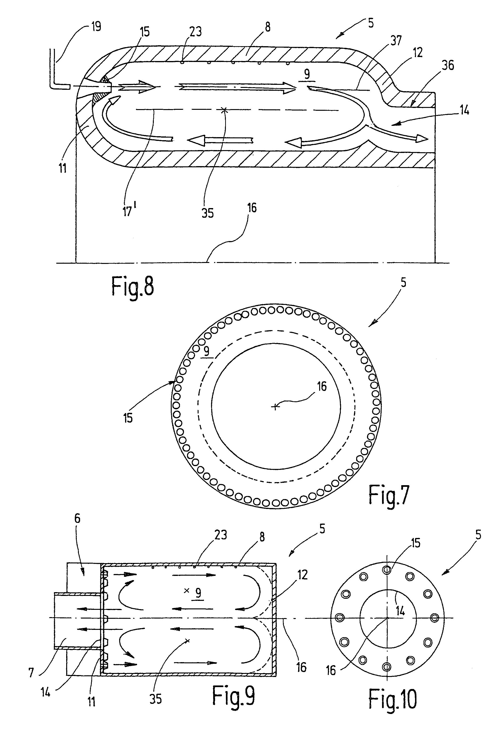
[0028]As shown in FIG. 2, the combustion chambers 5 can be roughly can-type burners which together form a combustion chamber set. A single such combustion chamber 5 is shown in FIG. 3. The combustion chamber has an internal space 9 enclosed by a wall 8, which is essentially cylindrical. On the inlet side, an end wall 11, which can be flat, is part of the wall 8. On the opposite side, an end wall 12 is formed in which an opening 14 with radius B that defines the outlet 7 is arranged. A series of air nozzles 15 that, as shown in FIG. 4, are arranged in a circle serves as the inlet 6. The air nozzles 15 are arranged in the vicinity of the w...


PUM


Abstract

A combustion chamber (5) for a gas turbine is adapted for flameless oxidation of fuels. This circulation flow has an internal space (9) in which a large-volume circulation flow is established. To this end, the combustion chamber supplies a hot exhaust stream to the introduced air, the mass flow rate of which exceeds the fresh air stream. The fresh air and the fuel are fed to the combustion chamber in the same direction, roughly parallel to the wall.

Description

FIELD OF THE INVENTION[0001]The invention relates to a combustion chamber for a gas turbine and a gas turbine equipped with such a combustion chamber.BACKGROUND OF THE INVENTION[0002]Gas turbines are used to convert heat energy to mechanical energy that can be delivered to a shaft (e.g., in a power plant, ship power plant, helicopter) or delivered as thrust (aircraft). All gas turbines have combustion chambers in which a fuel is burned with excess air. During combustion, a stable flame is formed in the combustion chamber. The gas flow, which has a very high velocity at the compressor outlet, is generally initially slowed for stabilization. Appropriate systems are provided to form stable flames. For example, small eddies are generated in the combustion chamber for flame stabilization. Combustion occurs with excess air so as not to cause thermal overload of the combustion chamber and turbine.[0003]Flameless oxidation of a fuel in a corresponding reaction space is known from EP 0463218...

Claims


Application Information

Patent Timeline
Patent Type & Authority Patents(United States)
IPC IPC(8): F02C1/00F23R3/10F23C9/00F23C99/00F23R3/16F23R3/28F23R3/42
CPCF23C9/006F23C99/00F23R3/42Y02E20/342F23R2900/03282F23C2900/99001Y02E20/34
Inventor WUNNING, JOACHIM G.WUNNING, JOACHIM A.
Owner WS WARMEPROZESSTECHN
Why Eureka
Try Eureka