Sampling tube-type smoke detector

a sampling tube and smoke detector technology, applied in fire alarms, specific gravity measurement, instruments, etc., can solve the problems of difficult miniaturization, difficult stabilization of target objectives, and specific limitations of sampling tube-type smoke detectors, and achieve the effect of suppressing airflow pressure loss

Inactive Publication Date: 2006-06-20
HOCHIKI CORP
View PDF23 Cites 19 Cited by
  • Summary
  • Abstract
  • Description
  • Claims
  • Application Information

AI Technical Summary

Benefits of technology

[0018]Further, in this invention, the lead-in tube is effective in suppressing the pressure loss of the airflow by vortex flow generated in the rotating part of the aspirator by being essentially formed in a substantially round shape.
[0019]In addition, according to this invention, the lead-in tube is made with a sequentially mutual wall side of the adjacent parts consisting of a segment formed in a substantially square-shape and a segment formed in a substantially round-shape, respectively. In order for the airflow of the lead-in tube to meet in a straight line with the connection part, they are formed together as one piece. As the flow path of the lead-in tube is designed to not produce a level difference, by forming the lead-in tube with the connection part as a mutually sequential smooth curved surface, airflow pressure loss can be suppressed.

Problems solved by technology

However, these conventional sampling tube-type smoke detectors have specific limitations which are described below.
On the other hand, within the constraints of the magnitude of the sampling tube-type smoke detector, target objective stabilization is problematic.
Furthermore, in the first conventional example, miniaturization is difficult as most of the main body is used as a chamber.
As the signal processing from the smoke sensor unit, the power circuit and the like are located external of the detector main body, a lot of space is required for the entire device.
However, due to a limitation in the bulkiness of the detector main body, the rotational axis of the fan of the aspirator is oriented so that it becomes the lead-in tube of the smoke detection device with an angle of 90 degrees approximately.

Method used


Image

  • Sampling tube-type smoke detector
  • Sampling tube-type smoke detector
  • Sampling tube-type smoke detector

Examples


Embodiment Construction

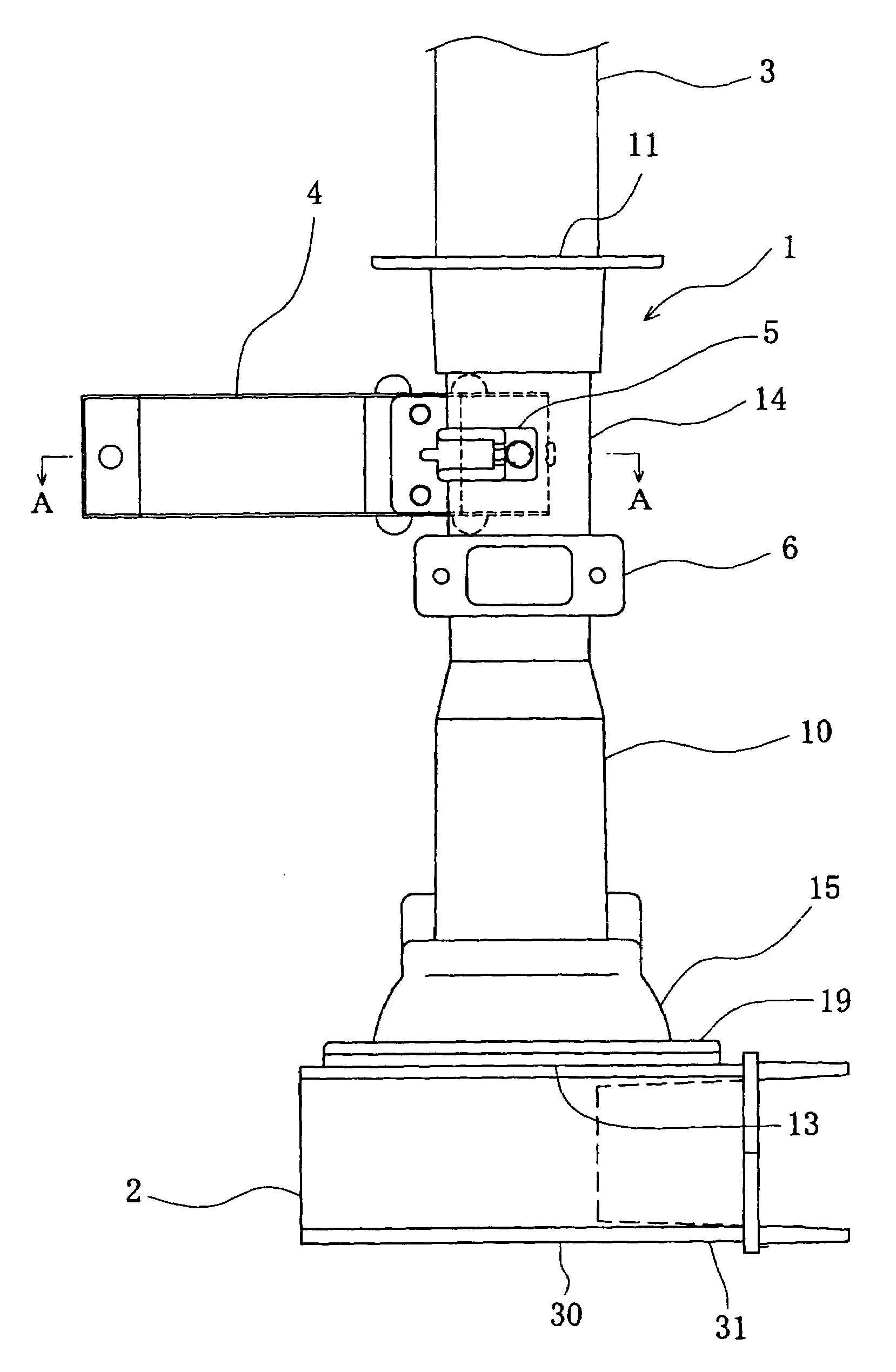
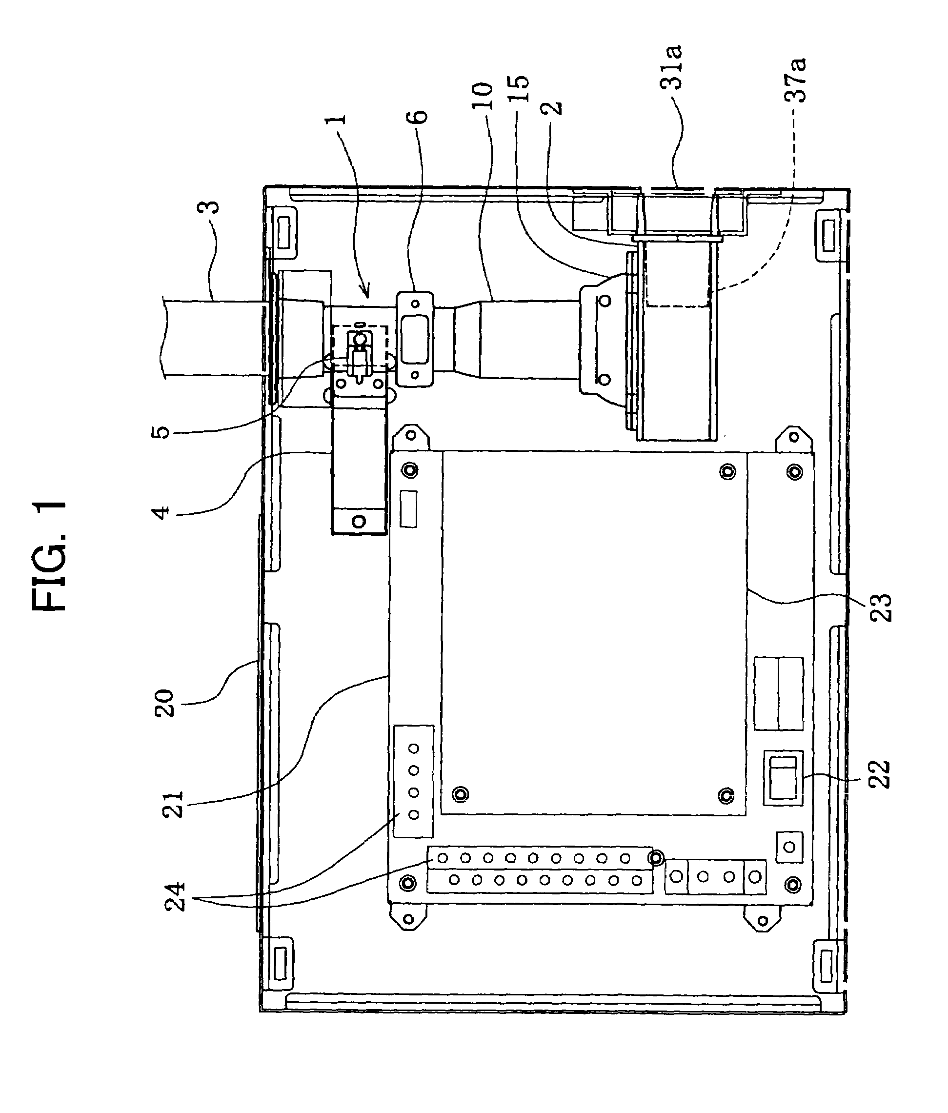
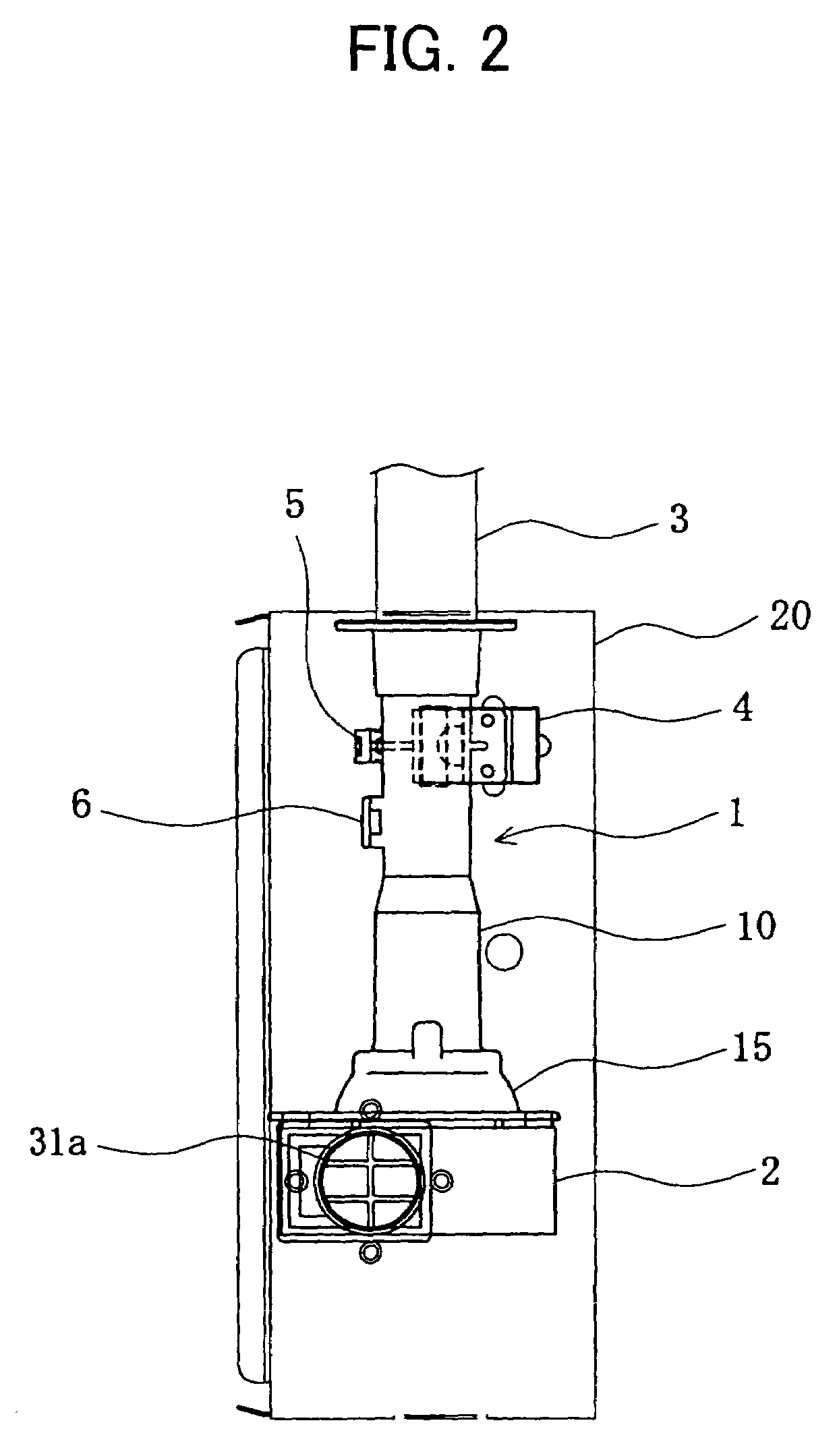
[0041]The present invention will hereinafter be described in detail with reference to the preferred embodiment shown in the accompanying drawings. FIG. 1 is a front elevation view showing the internal configuration of the detector main body in this embodiment. FIG. 2 is a right-hand side surface view of FIG. 1. FIG. 3 is a front elevation view of the smoke detection device in this embodiment. FIG. 4 is cross-sectional view of the lead-in tube which constitutes the smoke detection device and the inter-connection part.

[0042]The sampling tube-type smoke detector in this embodiment comprises a sampling tube 3 with suction openings 42 (see FIG. 7) formed in a monitored area. A smoke detection device 1 detects smoke particles contained in the air suctioned through the sampling tube 3. An aspirator 2 is formed in the downstream of the smoke detection device 1. The smoke detection device 1 and the aspirator 2 connect by way of an inter-connection part 15. Among those which constitute the sa...


PUM

PropertyMeasurementUnit
angleaaaaaaaaaa
diameteraaaaaaaaaa
diameteraaaaaaaaaa

Abstract

In a sampling tube-type smoke detector equipped with a smoke detection device detects smoke particles contained in the air suctioned from a monitored area through a sampling tube by an aspirator positioned in the downstream. The smoke detection device the sampling tube forms a lead-in tube and suctions air through the sampling tube in substantially a straight line. The lead-in tube is formed with a smoke sensor unit to detect smoke particles contained in the air. The aspirator comprises a rotating part which forms an actuator mechanism that discharges the air. The central axis of the lead-in tube and the rotational axis of the actuator mechanism of the aspirator are substantially on the same axis. The sampling tube-type smoke detector is provided to reduce pressure loss in the airflow traveling from the smoke detection device to the aspirator and to supply a low cost, compact smoke detection device driven by a small-sized fan.

Description

BACKGROUND OF THE INVENTION[0001]The present invention relates to a sampling tube-type smoke detector which suctions air into a sampling tube from a monitored area and optically detects smoke particles floating in the air using a laser beam, and more particularly to a sampling tube-type smoke detector which includes a smoke detection device and an aspirator aligned in a straight line and formed compactly.[0002]Conventionally, a high sensitivity smoke detector which detects slight smoke is used in a clean room, such as a computer room, in a hospital, a semiconductor manufacturing facility and the like. The highly sensitive smoke detector in this invention suctions air from a sampling tube (synonymous with pipe) installed in a monitored area and optically detects the number of particles floating in the air using a laser beam. Thus, a highly sensitive smoke detector with a sampling tube is hereafter designated a sampling tube-type smoke detector. As shown in FIG. 11, this sampling tube...

Claims


Application Information

Patent Timeline
Patent Type & Authority Patents(United States)
IPC IPC(8): G01N15/02G01N1/14G01N21/41G01N21/85G08B17/10G08B17/107
CPCG08B17/107G08B17/10G08B17/113
Inventor YAMANO, NAOTOEGAWA, YOSHITAKA
Owner HOCHIKI CORP
Why Eureka
Try Eureka